ASRock Fatal1ty 990FX Killer/3.1 User Manual - Page 40
Installation Procedure
 |
View all ASRock Fatal1ty 990FX Killer/3.1 manuals
Add to My Manuals
Save this manual to your list of manuals |
Page 40 highlights
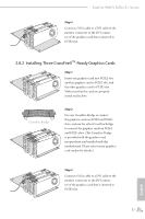
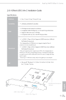
Installation Procedure he ASRock USB 3.1/A+C provides two external USB 3.1 ports which support transfer rates up to 10 Gbps. Follow the simple steps below to install the ASRock USB 3.1/A+C. Step 1 Power of the PC and unplug the power cord. Detach all other cables from the PC. Step 2 Remove the side panel from the computer case. *Refer to the documentation that comes with your PC for details. Step 3 Locate an available x4, x8 or x16 PCI Express slot on your motherboard and remove its slot bracket. *To maximize the performance of ASRock USB 3.1 /A+C, it is highly recommended to insert the card into the PCIE5 (from NB). Step 4 Align the ASRock USB 3.1/A+C with the PCI Express slot and press down irmly until it is fully seated in the slot. hen secure the card with the slot bracket's holding screw. Step 5 Replace the side panel. Reconnect the power cord and any other cables that were disconnected. *Jumper Setup: Jumper J1 is set to Pin1-2 by default and allows device charging during S3 (Sleep), S4 (Suspend) or S5 (Power Of) power states. To disable device charging during S3/ S4/S5 (Power Of) power states, you need to move the jumper cap placed on Pin1-2 (default) to Pin2-3. *Please install driver for Windows® 7 (32-bit and 64-bit). 32 English
-
 1
1 -
2
-
3
-
4
-
5
-
6
-
7
-
8
-
9
-
10
-
11
-
12
-
13
-
14
-
15
-
16
-
17
-
18
-
19
-
20
-
21
-
22
-
23
-
24
-
25
-
26
-
27
-
28
-
29
-
30
-
31
-
32
-
33
-
34
-
 35
35 -
 36
36 -
 37
37 -
 38
38 -
 39
39 -
 40
40 -
 41
41 -
 42
42 -
 43
43 -
 44
44 -
 45
45 -
46
-
47
-
48
-
49
-
50
-
51
-
52
-
53
-
54
-
55
-
56
-
57
-
58
-
59
-
60
-
61
-
62
-
63
-
64
-
65
-
66
-
67
-
68
-
69
-
70
-
71
-
72
-
73
-
74
-
75
-
76
-
77
-
78
-
79
-
80
-
81
-
82
-
83
-
84
 |
 |