ASRock Fatal1ty X299 Gaming K6 User Manual - Page 47
M.2_SSD (NGFF) Module Installation Guide, Installing the M.2_SSD NGFF Module
 |
View all ASRock Fatal1ty X299 Gaming K6 manuals
Add to My Manuals
Save this manual to your list of manuals |
Page 47 highlights
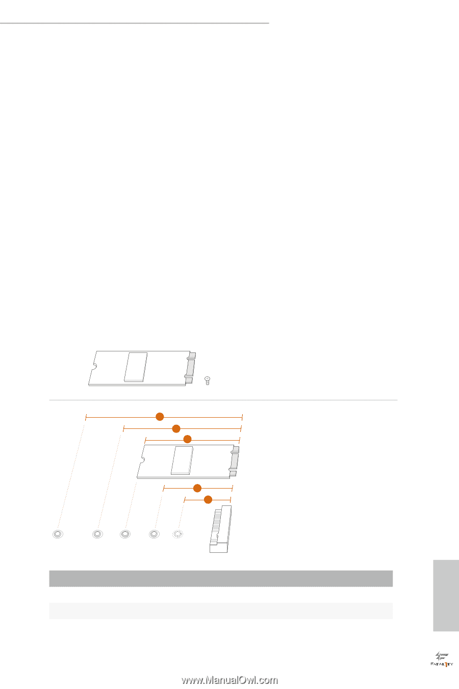
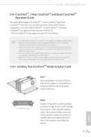
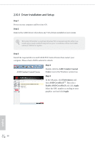
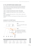
Fatal1ty X299 Gaming K6 Series 2.11 M.2_SSD (NGFF) Module Installation Guide The M.2, also known as the Next Generation Form Factor (NGFF), is a small size and versatile card edge connector that aims to replace mPCIe and mSATA. The Ultra M.2 Socket can accommodate either a M.2 SATA3 6.0 Gb/s module or a M.2 PCI Express module up to Gen3 x4 (32 Gb/s). * If M2_1 is occupied by a SATA-type M.2 device, SATA3_0 will be disabled. * If M2_2 is occupied by a SATA-type M.2 device, SATA3_1 will be disabled. * If M2_3 is occupied by a SATA-type M.2 device, SATA3_4 and SATA3_5 will be disabled. * If M2_3 is occupied by a PCIe-type M.2 device, SATA3_4, SATA3_5, SATA3_6 and SATA3_7 will be disabled. * If PCIE4 slot is occupied, M2_2 slot will support M.2 PCI Express module up to Gen3 x2 (16 Gb/s). Installing the M.2_SSD (NGFF) Module The following is an example of installing M.2_SSD (NGFF) module into the M2_2. Step 1 Prepare a M.2_SSD (NGFF) module and the screw. 5 4 3 2 1 Step 2 Depending on the PCB type and length of your M.2_SSD (NGFF) module, find the corresponding nut location to be used. English E D C B A No. Nut Location PCB Length Module Type 1 A 3cm Type2230 2 B 4.2cm Type 2242 3 C 6cm Type2260 4 D 8cm Type 2280 5 E 11cm Type 22110 39
-
 1
1 -
2
-
3
-
4
-
5
-
6
-
7
-
8
-
9
-
10
-
11
-
12
-
13
-
14
-
15
-
16
-
17
-
18
-
19
-
20
-
21
-
22
-
23
-
24
-
25
-
26
-
27
-
28
-
29
-
30
-
31
-
32
-
33
-
34
-
35
-
36
-
37
-
38
-
39
-
40
-
41
-
 42
42 -
 43
43 -
 44
44 -
 45
45 -
 46
46 -
 47
47 -
 48
48 -
 49
49 -
 50
50 -
 51
51 -
 52
52 -
53
-
54
-
55
-
56
-
57
-
58
-
59
-
60
-
61
-
62
-
63
-
64
-
65
-
66
-
67
-
68
-
69
-
70
-
71
-
72
-
73
-
74
-
75
-
76
-
77
-
78
-
79
-
80
-
81
-
82
-
83
-
84
-
85
-
86
-
87
-
88
-
89
-
90
-
91
-
92
-
93
-
94
-
95
-
96
-
97
-
98
-
99
-
100
-
101
-
102
-
103
-
104
-
105
 |
 |