ASRock Fatal1ty X79 Professional User Manual - Page 15
LAN Port LED Indications, TABLE for Audio Output, Connection
 |
View all ASRock Fatal1ty X79 Professional manuals
Add to My Manuals
Save this manual to your list of manuals |
Page 15 highlights
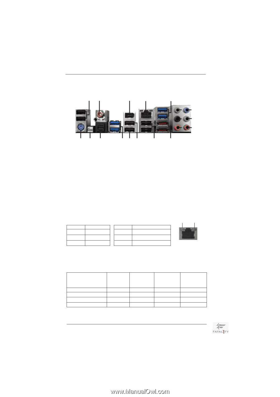
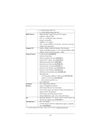
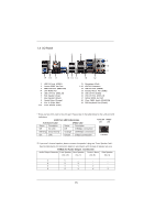
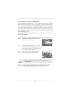
1.4 I/O Panel 12 3 4 5 69 7 10 8 11 19 18 17 16 15 14 13 12 1 2 3 * 4 5 6 7 8 9 ** 10 USB 2.0 Ports (USB01) Coaxial SPDIF Out Port IEEE 1394 Port (IEEE 1394) LAN RJ-45 Port USB 3.0 Ports (USB3_34) Side Speaker (Gray) Rear Speaker (Black) Central / Bass (Orange) Line In (Light Blue) Front Speaker (Lime) 11 *** 12 13 14 15 16 17 18 19 Microphone (Pink) eSATA3 Connectors USB 2.0 Ports (USB45) Fatal1ty Mouse Port (USB2) USB 2.0 Port (USB3) USB 3.0 Ports (USB3_12) Optical SPDIF Out Port Clear CMOS Switch (CLRCBTN) PS/2 Keyboard Port (Purple) * There are two LEDs next to the LAN port. Please refer to the table below for the LAN port LED indications. LAN Port LED Indications Activity/Link LED SPEED LED ACT/LINK SPEED LED LED Status Description Status Description Off No Link Off 10Mbps connection Blinking Data Activity Orange 100Mbps connection On Link Green 1Gbps connection LAN Port ** If you use 2-channel speaker, please connect the speaker's plug into "Front Speaker Jack". See the table below for connection details in accordance with the type of speaker you use. TABLE for Audio Output Connection Audio Output Channels Front Speaker Rear Speaker Central / Bass Side Speaker (No. 10) (No. 7) (No. 8) (No. 6) 2 V -- -- -- 4 V V -- -- 6 V V V -- 8 V V V V 15
-
 1
1 -
2
-
3
-
4
-
5
-
6
-
7
-
8
-
9
-
 10
10 -
 11
11 -
 12
12 -
 13
13 -
 14
14 -
 15
15 -
 16
16 -
 17
17 -
 18
18 -
 19
19 -
 20
20 -
21
-
22
-
23
-
24
-
25
-
26
-
27
-
28
-
29
-
30
-
31
-
32
-
33
-
34
-
35
-
36
-
37
-
38
-
39
-
40
-
41
-
42
-
43
-
44
-
45
-
46
-
47
-
48
-
49
-
50
-
51
-
52
-
53
-
54
-
55
-
56
-
57
-
58
-
59
-
60
-
61
-
62
-
63
-
64
-
65
-
66
-
67
-
68
-
69
-
70
-
71
-
72
-
73
-
74
-
75
-
76
-
77
-
78
-
79
-
80
-
81
-
82
-
83
-
84
-
85
-
86
-
87
 |
 |