ASRock Fatal1ty X99 Professional/3.1 User Manual
ASRock Fatal1ty X99 Professional/3.1 Manual
 |
View all ASRock Fatal1ty X99 Professional/3.1 manuals
Add to My Manuals
Save this manual to your list of manuals |
ASRock Fatal1ty X99 Professional/3.1 manual content summary:
- ASRock Fatal1ty X99 Professional/3.1 | User Manual - Page 1
- ASRock Fatal1ty X99 Professional/3.1 | User Manual - Page 2
documentation are furnished for informational use only and subject to change without notice, and should not be constructed as a commitment by ASRock. ASRock assumes no responsibility for any errors or omissions that may appear in this documentation. With respect to the contents of this documentation - ASRock Fatal1ty X99 Professional/3.1 | User Manual - Page 3
Manufactured under license under U.S. Patent Nos: 5,956,674; 5,974,380; 6,487,535; 7,003,467 & other U.S. and worldwide patents issued & pending. DTS, the Symbol, & DTS and the Symbol together is a registered trademark & DTS Connect, DTS Interactive, DTS Neo:PC are trademarks of DTS, Inc. Product - ASRock Fatal1ty X99 Professional/3.1 | User Manual - Page 4
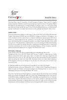
Fatal1ty Story Who knew that at age 19, I would be a World Champion PC gamer. When I was 13, I actually played competitive billiards in professional challenging matches and earning $25,000 for the victory. Since then Fatal1ty has traveled the globe to compete against the best in the world - ASRock Fatal1ty X99 Professional/3.1 | User Manual - Page 5
my drive to be the best has opened the doors necessary to become a professional. A DREAM Now, another dream is being realized - building the ultimate gaming and allowing more fluid movement around the maps. My vision for Fatal1ty hardware is to allow gamers to focus on the game without worrying - ASRock Fatal1ty X99 Professional/3.1 | User Manual - Page 6
36 2.10.3 Installing Four SLITM-Ready Graphics Cards 38 2.10.4 Driver Installation and Setup 40 2.11 CrossFireXTM, 3-Way CrossFireXTM , 4-Way CrossFireXTM and Quad CrossFireXTM Operation Guide 41 2.11.1 Installing Two CrossFireXTM-Ready Graphics Cards 41 - ASRock Fatal1ty X99 Professional/3.1 | User Manual - Page 7
Cards 43 2.11.4 Driver Installation and Setup 44 2.12 M.2_SSD (NGFF) Module Installation Guide 45 2.13 HDD Saver Cable Installation Guide 48 2.14 ASRock USB 3.1 Card/A+A Installation Guide 49 Chapter 3 Software and Utilities Operation 51 3.1 Installing Drivers 51 3.2 F-Stream 52 - ASRock Fatal1ty X99 Professional/3.1 | User Manual - Page 8
Chapter 4 UEFI SETUP UTILITY 77 4.1 Introduction 77 4.1.1 UEFI Menu Bar 77 4.1.2 Navigation Keys 78 4.2 Main Screen 79 4.3 OC Tweaker Screen 80 4.4 Advanced Screen 90 4.4.1 CPU Configuration 91 4.4.2 Chipset Configuration 93 4.4.3 Storage Configuration 96 4.4.4 Super IO - ASRock Fatal1ty X99 Professional/3.1 | User Manual - Page 9
CPU support list on ASRock's website as well. ASRock website http://www.asrock.com. 1.1 Package Contents • ASRock Fatal1ty X99 Professional Series Motherboard (EATX Form Factor) • ASRock Fatal1ty X99 Professional Series Quick Installation Guide • ASRock Fatal1ty X99 Professional Series Support CD - ASRock Fatal1ty X99 Professional/3.1 | User Manual - Page 10
Untied Overclocking Technology Chipset • Intel® X99 Memory • Quad Channel DDR4 Memory Technology • 8 x DDR4 DIMM Slots • Supports DDR4 3400+(OC)*/2933(OC)/2800(OC)/2400( OC)/2133 non-ECC, un-buffered memory * Please refer to Memory Support List on ASRock's website for more information. (http - ASRock Fatal1ty X99 Professional/3.1 | User Manual - Page 11
Fatal1ty X99 Professional/3.1 Series * If Ultra M.2 PCI Express module is installed, PCIE3 slot will be disabled. • 1 x Half Mini-PCI Express Slot • Supports AMD Quad CrossFireXTM, 4-Way CrossFireXTM, 3-Way CrossFireXTM and CrossFireXTM • Supports NVIDIA® Quad SLITM, 4-Way SLITM, 3-Way SLITM and - ASRock Fatal1ty X99 Professional/3.1 | User Manual - Page 12
• 1 x Fatal1ty Mouse Port (USB 2.0) (Supports ESD Protection (ASRock Full Spike Protection)) • 1 x USB 2.0 Port (Supports ESD Protection (ASRock Full Spike Protection)) • 1 x USB 3.1 Type-C Port (10 Gb/s) (Supports ESD Protection (ASRock Full Spike Protection)) • 4 x USB 3.0 Ports (ASMedia ASM1074 - ASRock Fatal1ty X99 Professional/3.1 | User Manual - Page 13
Fatal1ty X99 Professional/3.1 Series BIOS Feature Hardware Monitor • 1 x 24 pin ATX support 4 USB 2.0 ports) (Supports ESD Protection (ASRock Full Spike Protection)) • 1 x Vertical Type A USB 3.0 • 2 x USB 3.0 Headers (Support 4 USB 3.0 ports) (ASMedia ASM1074 hub) (Supports ESD Protection (ASRock - ASRock Fatal1ty X99 Professional/3.1 | User Manual - Page 14
, CE, WHQL • ErP/EuP Ready (ErP/EuP ready power supply is required) * For detailed product information, please visit our website: http://www.asrock.com Please realize that there is a certain risk involved with overclocking, including adjusting the setting in the BIOS, applying Untied Overclocking - ASRock Fatal1ty X99 Professional/3.1 | User Manual - Page 15
Fatal1ty X99 Professional/3.1 Series 1.3 Motherboard Layout 12 3 4 5 67 8 USB 2.0 T: USB1 B: USB2 PS2 21 22 23 S_SATA3_2_3 SATA3_0_3 MINI_PCIE1 PCIE2 24 SATA3_1_4 PCIE3 Intel 25 X99 Professional/3.1 X99 PCIE4 26 SATA3_2_5 SATAE_1 Ultra M.2 PCIe Gen3 x4 ULTRA_M2 Purity SoundTM - ASRock Fatal1ty X99 Professional/3.1 | User Manual - Page 16
No. Description 1 2 x 284-pin DDR4 DIMM Slots (DDR4_A1, DDR4_B1) 2 2 x 284-pin DDR4 DIMM Slots (DDR4_A2, DDR4_B2) 3 8 pin ATX 12V Power Connector (ATX12V1) 4 4 pin ATX 12V Power Connector (ATX12V2) 5 CPU Fan Connector (CPU_FAN1) 6 2 x 284-pin DDR4 DIMM Slots (DDR4_D2, DDR4_C2) 7 2 x 284-pin DDR4 - ASRock Fatal1ty X99 Professional/3.1 | User Manual - Page 17
COM Port Header (COM1) 43 PCIe Power Connector (PCIE_PWR1) 44 Thunderbolt AIC Connector (TB1) 45 Front Panel Audio Header (HD_AUDIO1) 46 Power Fan Connector (PWR_FAN1) Fatal1ty X99 Professional/3.1 Series English 9 - ASRock Fatal1ty X99 Professional/3.1 | User Manual - Page 18
1.4 I/O Panel 1 2 46 3 57 16 15 14 13 12 11 10 98 No. Description No. Description 1 Fatal1ty Mouse Port (USB1) 11 USB 3.1 Type-C Port (USB31_TC_1) 2 USB 2.0 Port (USB2) (ASMedia ASM1142) 3 LAN RJ-45 Port 12 USB 3.0 Ports (USB3_34) (Qualcomm® Atheros® KillerTM E2200 - ASRock Fatal1ty X99 Professional/3.1 | User Manual - Page 19
Fatal1ty X99 Professional/3.1 Series * There are two LEDs on each LAN port. Please refer to the table below for the LAN port LED indications. ACT/LINK LED SPEED - ASRock Fatal1ty X99 Professional/3.1 | User Manual - Page 20
Chapter 2 Installation This is an EATX form factor motherboard. Before you install the motherboard, study the configuration of your chassis to ensure that the motherboard fits into it. Pre-installation Precautions Take note of the following precautions before you install motherboard components or - ASRock Fatal1ty X99 Professional/3.1 | User Manual - Page 21
Fatal1ty X99 Professional/3.1 Series 2.1 Installing the CPU 1. Before you insert the will be seriously damaged. 2. Unplug all power cables before installing the CPU. CAUTION: Please note that X99 platform is only compatible with the LGA 2011-3 socket, which is incompatible with the LGA 2011 socket ( - ASRock Fatal1ty X99 Professional/3.1 | User Manual - Page 22
A 3 B 4 5 14 English - ASRock Fatal1ty X99 Professional/3.1 | User Manual - Page 23
Fatal1ty X99 Professional/3.1 Series 6 A B 7 A B 8 Please save and replace the cover if the processor is removed. The cover must be placed if you wish to return the motherboard for after service. 15 English - ASRock Fatal1ty X99 Professional/3.1 | User Manual - Page 24
2.2 Installing the CPU Fan and Heatsink 1 16 2 CPU_FAN English - ASRock Fatal1ty X99 Professional/3.1 | User Manual - Page 25
Fatal1ty X99 Professional/3.1 Series 2.3 Installation of Memory Modules (DIMM) This motherboard provides eight 284-pin DDR4 (Double Data Rate 4) DIMM slots, and supports Quad Channel Memory Technology. 1. For quad channel configuration, you always need to install identical (the same brand, speed, - ASRock Fatal1ty X99 Professional/3.1 | User Manual - Page 26
1 2 3 18 English - ASRock Fatal1ty X99 Professional/3.1 | User Manual - Page 27
Fatal1ty X99 Professional/3.1 Series 2.4 Expansion Slots (PCI Express Slots) There are 5 PCI Express slots and 1 mini-PCI Express slot on the motherboard. Before installing an expansion card, please - ASRock Fatal1ty X99 Professional/3.1 | User Manual - Page 28
x8 N/A Three Graphics Cards in 3-Way CrossFireXTM Mode x8 or 3-Way SLITM Mode x8 N/A x8 N/A *4-Way CrossFireXTM and 4-Way SLITM are not supported for CPU with 28 PCIe lanes. For a better thermal environment, please connect a chassis fan to the motherboard's chassis fan connector (CHA_FAN1 - ASRock Fatal1ty X99 Professional/3.1 | User Manual - Page 29
Fatal1ty X99 Professional/3.1 Series 2.5 Jumpers Setup The illustration shows how jumpers are setup. When the jumper cap is placed on the pins, the jumper is "Short". If no - ASRock Fatal1ty X99 Professional/3.1 | User Manual - Page 30
2.6 Onboard Headers and Connectors Onboard headers and connectors are NOT jumpers. Do NOT place jumper caps over these headers and connectors. Placing jumper caps over the headers and connectors will cause permanent damage to the motherboard. System Panel Header (9-pin PANEL1) (see p.7, No. 33) - ASRock Fatal1ty X99 Professional/3.1 | User Manual - Page 31
Fatal1ty X99 Professional/3.1 Series Serial ATA3 Connectors (S_SATA3_0_1: see p.7, No. 22) (S_SATA3_2_3: see p.7, SATA3_1 SATA3_0 S_SATA3_2 S_SATA3_0 SATA3_5 SATA3_4 SATA3_3 S_SATA3_3 S_SATA3_1 These ten SATA3 connectors support SATA data cables for internal storage devices with up to 6.0 Gb/s - ASRock Fatal1ty X99 Professional/3.1 | User Manual - Page 32
for connecting audio devices to the front audio panel. 1. High Definition Audio supports Jack Sensing, but the panel wire on the chassis must support HDA to function correctly. Please follow the instructions in our manual and chassis manual to install your system. 2. If you use an AC'97 audio panel - ASRock Fatal1ty X99 Professional/3.1 | User Manual - Page 33
Fatal1ty X99 Professional/3.1 Series Chassis and Power Fan Connectors (4-pin CHA_FAN1) (see p.7, No. 40) (3-pin CHA_FAN2) (see p.7, No. 36) (3-pin CHA_FAN3) (see p.7, No. 20) (3-pin PWR_FAN1) (see p.7, No. - ASRock Fatal1ty X99 Professional/3.1 | User Manual - Page 34
the GPIO cable. *Please install the Thunderbolt™ AIC card to PCIE3 (default slot). RRXD1 DDTR#1 DDSR#1 CCTS#1 1 RRI#1 RRTS#1 GND TTXD1 DDCD#1 This COM1 header supports a serial port module. English 26 - ASRock Fatal1ty X99 Professional/3.1 | User Manual - Page 35
Header (17-pin TPMS1) (see p.7, No. 37) 1 GN D SMB_CLK_MAIN SMB_DATA_MAIN LAD2 LAD1 GN D S_PWRDWN # SERIRQ # GND Fatal1ty X99 Professional/3.1 Series This connector supports Trusted Platform Module (TPM) system, which can securely store keys, digital certificates, passwords, and data. A TPM system - ASRock Fatal1ty X99 Professional/3.1 | User Manual - Page 36
2.7 Smart Switches The motherboard has eleven smart switches: Power Switch, Reset Switch, Clear CMOS Switch, Rapid OC Buttons, Menu Button, PCIe ON/OFF Switch, Slow Mode Switch, BIOS Selection Switch, LN2 Mode Switch and Direct Key Button. Power Switch (PWR) (see p.7, No. 34) Power Power Switch - ASRock Fatal1ty X99 Professional/3.1 | User Manual - Page 37
Fatal1ty X99 Professional/3.1 Series PCIe ON/OFF Switch (PCIE_SWITCH) (see p.7, No. 12) 1234 1: PCIE1 2: PCIE2 . For safety issues, users are not able to update the backup BIOS manually. Users may refer to the BIOS LEDs (BIOS_A_LED or BIOS_B_LED) to identify which BIOS is currently activated - ASRock Fatal1ty X99 Professional/3.1 | User Manual - Page 38
ON OFF English LN2 Mode Switch (LN2MODE) (see p.7, No. 13) Direct Key Button (DIRKEY1) (see p.7, No. 31) The LN2 mode aids in eliminating the cold-boot bug issues in processors during extreme overclocking with Liquid Nitrogen. Direct Key Button allows users to turn on the system and directly enter - ASRock Fatal1ty X99 Professional/3.1 | User Manual - Page 39
Fatal1ty X99 Professional/3.1 Series 2.8 Dr. Debug Dr. Debug is used to provide code information, which makes troubleshooting even easier. could not be detected. Please re-install the memory and CPU. If the problem still exists, please install only one memory module or try using other memory - ASRock Fatal1ty X99 Professional/3.1 | User Manual - Page 40
or try using other memory modules. d6 The VGA could not be recognized. Please clear CMOS and try re-installing the VGA card. If the problem still exists, please try installing the VGA card in other slots or use other VGA cards. d7 The Keyboard and mouse could not be recognized - ASRock Fatal1ty X99 Professional/3.1 | User Manual - Page 41
Fatal1ty X99 Professional/3.1 Series 2.9 Post Status Checker Post Status Checker (PSC) diagnoses the computer when users power on the machine. It emits a red light to indicate whether the - ASRock Fatal1ty X99 Professional/3.1 | User Manual - Page 42
3-Way SLITM , 4-Way SLITM and Quad SLITM Operation Guide This motherboard supports NVIDIA® SLITM , 3-way SLITM, 4-way SLITM and cards that are NVIDIA® certified. 2. Make sure that your graphics card driver supports NVIDIA® SLITM technology. Download the drivers from the NVIDIA® website: www.nvidia. - ASRock Fatal1ty X99 Professional/3.1 | User Manual - Page 43
Fatal1ty X99 Professional/3.1 Series Step 3 Align and insert the ASRock SLI_ Bridge_3S Card to the goldfingers on each graphics card. Make sure the ASRock SLI_ Bridge_3S Card is firmly in place. SLI_Bridge_3S Card ASRock SLI_Bridge_3S Card Step 4 Connect a VGA cable or a DVI cable to the monitor - ASRock Fatal1ty X99 Professional/3.1 | User Manual - Page 44
that both power connectors on the PCI Express graphics card are connected. Repeat this step on the three graphics cards. Step 3 Align and insert the ASRock 3-Way SLI Bridge Card to the goldfingers on each graphics card. Make sure the - ASRock Fatal1ty X99 Professional/3.1 | User Manual - Page 45
Fatal1ty X99 Professional/3.1 Series Step 4 Connect a VGA cable or a DVI cable to the monitor connector or the DVI connector of the graphics card that is inserted to PCIE1 slot. 37 English - ASRock Fatal1ty X99 Professional/3.1 | User Manual - Page 46
. Repeat this step on the three graphics cards. SLI_Bridge_3S Card Step 3 Align and insert an ASRock SLI Bridge Card to the goldfingers of the first and second graphics card. Install the second ASRock SLI Bridge Card to the goldfingers of the third and fourth graphics card. Connect the second and - ASRock Fatal1ty X99 Professional/3.1 | User Manual - Page 47
Fatal1ty X99 Professional/3.1 Series Step 4 Connect a VGA cable or a DVI cable to the monitor connector or the DVI connector of the graphics card that is inserted to PCIE1 slot. 39 English - ASRock Fatal1ty X99 Professional/3.1 | User Manual - Page 48
2.10.4 Driver Installation and Setup Install the graphics card drivers to your system. After that, you can enable the Multi-Graphics Processing Unit (GPU) in the NVIDIA® nView system tray utility. Please follow the below procedures to enable the multi-GPU. Step 1 Double-click the NVIDIA Control - ASRock Fatal1ty X99 Professional/3.1 | User Manual - Page 49
Fatal1ty X99 Professional/3.1 Series 2.11 CrossFireXTM, 3-Way CrossFireXTM , 4-Way CrossFireXTM and Quad CrossFireXTM Operation Guide This motherboard supports CrossFireXTM. Please refer to AMD graphics card manuals for detailed installation guide. 2.11.1 Installing Two CrossFireXTM-Ready Graphics - ASRock Fatal1ty X99 Professional/3.1 | User Manual - Page 50
Step 3 Connect a VGA cable or a DVI cable to the monitor connector or the DVI connector of the graphics card that is inserted to PCIE1 slot. 2.11.2 Installing Three CrossFireXTM-Ready Graphics Cards Step 1 Insert one graphics card into PCIE1 slot, another graphics card to PCIE2 slot, and the other - ASRock Fatal1ty X99 Professional/3.1 | User Manual - Page 51
Fatal1ty X99 Professional/3.1 Series 2.11.3 Installing Four CrossFireXTM-Ready Graphics Cards Step 1 Insert one graphics card into PCIE1 slot, another graphics card into PCIE2 slot, the third graphics - ASRock Fatal1ty X99 Professional/3.1 | User Manual - Page 52
2.11.4 Driver Installation and Setup Step 1 Power on your computer and boot into OS. Step 2 Remove the AMD drivers if you have any VGA drivers installed in your system. The Catalyst Uninstaller is an optional download. We recommend using this utility to uninstall any previously installed Catalyst - ASRock Fatal1ty X99 Professional/3.1 | User Manual - Page 53
Fatal1ty X99 Professional/3.1 Series 2.12 M.2_SSD (NGFF) Module Installation Guide The M.2 (M2_1), also known as the Next Generation Form Factor (NGFF), is a small size and versatile card edge connector that aims to replace mPCIe and - ASRock Fatal1ty X99 Professional/3.1 | User Manual - Page 54
E D C B A E D C B A C B A E D C B A E D NUT2 NUT1 Step 3 Move the standoff based on the module type and length. The standoff is placed at the nut location D by default. Skip Step 3 and 4 and go straight to Step 5 if you are going to use the default nut. Otherwise, release the - ASRock Fatal1ty X99 Professional/3.1 | User Manual - Page 55
Fatal1ty X99 Professional/3.1 Series M.2_SSD (NGFF) Module Support List PCIe Interface SATA Interface Plextor PX-G512M6e Plextor PX-G256M6e RBU-SM2280S3/120G For the latest updates of M.2_SSD (NFGG) module support list, please visit our website for details: http://www.asrock.com English 47 - ASRock Fatal1ty X99 Professional/3.1 | User Manual - Page 56
2.13 HDD Saver Cable Installation Guide The HDD Saver Connector on this motherboard allows you to near the SATA ports. Then connect the SATA power connector(s) to your SATA HDD(s). * The HDD Saver Connector supports up to two SATA HDDs. 2. Connect one end of the SATA data cable to a SATA port on the - ASRock Fatal1ty X99 Professional/3.1 | User Manual - Page 57
Fatal1ty X99 Professional/3.1 Series 2.14 ASRock USB 3.1 Card/A+A Installation Guide Specifications Platform • Size: 3.1-in x 2 x USB 3.1 Type-A Ports (Supports ESD Protection (ASRock Full Spike Protection)) *Sleep Mode (S3/S4/S5) Wake-up function is not supported. • 1 x 4-pin Power Connector - ASRock Fatal1ty X99 Professional/3.1 | User Manual - Page 58
external USB 3.1 ports which support transfer rates up to 10 Gbps. Follow the simple steps below to install the ASRock USB 3.1 Card/A+A. Step 1 your motherboard and remove its slot bracket. *To maximize the performance of ASRock USB 3.1/A+A, it is highly recommended to insert the card into the PCIE3 - ASRock Fatal1ty X99 Professional/3.1 | User Manual - Page 59
Fatal1ty X99 Professional/3.1 Series Chapter 3 Software and Utilities Operation 3.1 Installing Drivers The Support CD that comes with the motherboard contains necessary drivers and useful utilities that enhance the motherboard's features. Running The Support CD To begin using the support CD, insert - ASRock Fatal1ty X99 Professional/3.1 | User Manual - Page 60
Installing F-Stream When you install the all-in-one driver to your system from ASRock's support CD, F-Stream will be auto-installed as well. After the installation, you will System Info, Live Update, Tech Service and Settings. Operation Mode Choose an operation mode for your computer. 52 English - ASRock Fatal1ty X99 Professional/3.1 | User Manual - Page 61
Tools Various tools and utilities. Fatal1ty X99 Professional/3.1 Series XFast RAM Boost the system's performance and extend computer's boot time. Please note that Ultra Fast mode is only supported by Windows 8.1/8 and the VBIOS must support UEFI GOP if you are using an external graphics card. OMG - ASRock Fatal1ty X99 Professional/3.1 | User Manual - Page 62
disk model, serial number, firmware, power on count, power on hours, S.M.A.R.T. values, current temperature, etc. HDD, SSD and optical disk drives are all supported. The health status block displays Good (in green color), Caution (in yellow color) or Bad (in red color). Click on the health status - ASRock Fatal1ty X99 Professional/3.1 | User Manual - Page 63
OC Tweaker Configurations for overclocking the system. Fatal1ty X99 Professional/3.1 Series System Info View information about the system. English 55 - ASRock Fatal1ty X99 Professional/3.1 | User Manual - Page 64
Multi Thermal Sensor It provides users the temperature of various parts of the motherboard graphically, so that users may precisely keep track and control of the temperature of each parts of their motherboard when overclocking. System Browser System Browser shows the overview of your current PC and - ASRock Fatal1ty X99 Professional/3.1 | User Manual - Page 65
Fatal1ty X99 Professional/3.1 Series Tech Service Contact Tech Service if you have problems with your computer. Please leave your contact information along with details of the problem. Settings Configure ASRock F-Stream. Click to select "Auto run at Windows Startup" if you want F-Stream to be - ASRock Fatal1ty X99 Professional/3.1 | User Manual - Page 66
for all network traffic to fit your needs. 3.3.1 Installing Killer Network Manager When you install the all-in-one driver to your system from ASRock's support CD, Killer Network Manager will be auto-installed as well. After the installation, you will find the icon "Killer Network Manager" on your - ASRock Fatal1ty X99 Professional/3.1 | User Manual - Page 67
Fatal1ty X99 Professional/3.1 Series Performance Performance allows you to view in real time your system performance and current network utilization for download and upload traffic. Network Network allows - ASRock Fatal1ty X99 Professional/3.1 | User Manual - Page 68
Killer Ethernet Killer Ethernet displays the network information. 60 English - ASRock Fatal1ty X99 Professional/3.1 | User Manual - Page 69
Fatal1ty X99 Professional/3.1 Series 3.4 ASRock APP Shop The ASRock APP Shop is an online store for purchasing and downloading software applications for your ASRock computer. You can install various apps and support utilities quickly and easily, and optimize your system and keep your motherboard up - ASRock Fatal1ty X99 Professional/3.1 | User Manual - Page 70
3.4.2 Apps When the "Apps" tab is selected, you will see all the available apps on screen for you to download. Installing an App Step 1 Find the app you want to install. The most recommended app appears on the left side of the screen. The other various apps are shown on the right. Please scroll up - ASRock Fatal1ty X99 Professional/3.1 | User Manual - Page 71
Fatal1ty X99 Professional/3.1 Series Step 3 If you want to install the app, click on the red icon to start downloading. Step 4 When installation completes, you can find the - ASRock Fatal1ty X99 Professional/3.1 | User Manual - Page 72
Upgrading an App You can only upgrade the apps you have already installed. When there is an available new version for your app, you will find the mark of "New Version" appears below the installed app icon. Step 1 Click on the app icon to see more details. Step 2 Click on the yellow icon to start - ASRock Fatal1ty X99 Professional/3.1 | User Manual - Page 73
Fatal1ty X99 Professional/3.1 Series 3.4.3 BIOS & Drivers Installing BIOS or Drivers When the "BIOS & Drivers" tab is selected, you will see a list of recommended or critical updates for the - ASRock Fatal1ty X99 Professional/3.1 | User Manual - Page 74
3.4.4 Setting In the "Setting" page, you can change the language, select the server location, and determine if you want to automatically run the ASRock APP Shop on Windows startup. 66 English - ASRock Fatal1ty X99 Professional/3.1 | User Manual - Page 75
Fatal1ty X99 Professional/3.1 Series 3.5 Start8 For those Windows 8 users who miss the Start Menu, Start8 Install Start8, which is located in the folder at the following path of the Support CD: \ ASRock Utility > Start8. 3.5.2 Configuring Start8 Style Select between the Windows 7 style and Windows - ASRock Fatal1ty X99 Professional/3.1 | User Manual - Page 76
Configure Configure provides configuration options, including icon sizes, which shortcuts you want Start Menu to display, quick access to recently used apps, the functionality of the power button, and more. Control 68 English - ASRock Fatal1ty X99 Professional/3.1 | User Manual - Page 77
Fatal1ty X99 Professional/3.1 Series Control lets you configure what a click on the start button or a press on the Windows key does. Desktop Desktop allows you to disable the - ASRock Fatal1ty X99 Professional/3.1 | User Manual - Page 78
system and find their CPU's best margin. *For Windows 7 and above Step 1 Double-click software. Step 2 on your desktop to launch the ASRock Rapid OC Configuration The Rapid OC Configuration screen appears. English • Rapid OC Active: Enable the Rapid OC configuration function and you can press - ASRock Fatal1ty X99 Professional/3.1 | User Manual - Page 79
Fatal1ty X99 Professional/3.1 Series • Minus(-): Decrease the value of the selected item • Menu: Press the hotkey to select among configuration options (OC mode). On the screen, you can - ASRock Fatal1ty X99 Professional/3.1 | User Manual - Page 80
3.7 Timing Configurator Timing Configurator* is a fast and easy tool that provides users an overview of abundant collection of subtle DRAM settings. You won't even have to waste time on entering into the UEFI or restarting the system, Timing Configurator is an independent application that runs under - ASRock Fatal1ty X99 Professional/3.1 | User Manual - Page 81
Fatal1ty X99 Professional/3.1 Series 3.8 XSplit Broadcaster XSplit Broadcaster is a desktop application designed to make your multimedia broadcasting, live-streaming and recording a lot easier and more fun to do, - ASRock Fatal1ty X99 Professional/3.1 | User Manual - Page 82
Step 3 Go to Broadcast > Add Channels.... Step 4 Click Add.... Step 5 Select a platform for live streaming. *Before you start streaming, you need to register an account for the streaming service website, such as Twitch.tv, USTREAM, or other livestreaming services. 74 English - ASRock Fatal1ty X99 Professional/3.1 | User Manual - Page 83
Fatal1ty X99 Professional/3.1 Series Step 6 Fill in your platform's Username and Password. Based on your needs, configure the Video and Audio Encoding settings. Click OK. Step 7 The channel then appears in your broadcast list. Click Apply and OK to save the settings. 75 English - ASRock Fatal1ty X99 Professional/3.1 | User Manual - Page 84
Step 8 Go to Broadcast and select the platform to enable live streaming. A link to view your live Broadcast has been copied for you automatically. Simply press CTRL-V or right click and choose Paste to paste the link into the browser, and you can see your broadcast. To disable live streaming, go to - ASRock Fatal1ty X99 Professional/3.1 | User Manual - Page 85
Fatal1ty X99 Professional/3.1 Series Chapter 4 UEFI SETUP UTILITY 4.1 Introduction This section explains how to use the UEFI Setup Utility to configure your system. You may run the UEFI - ASRock Fatal1ty X99 Professional/3.1 | User Manual - Page 86
4.1.2 Navigation Keys Use < > key or < > key to choose among the selections on the menu bar, and use < > key or < > key to move the cursor up or down to select items, then press to get into the sub screen. You can also use the mouse to click your required item. Please check the following - ASRock Fatal1ty X99 Professional/3.1 | User Manual - Page 87
Fatal1ty X99 Professional/3.1 Series 4.2 Main Screen When you enter the UEFI Setup Utility, the Main screen will appear and display the system overview. My Favorite Display your collection of BIOS items. Press F5 to add/remove your favorite items. 79 English - ASRock Fatal1ty X99 Professional/3.1 | User Manual - Page 88
you see on your screen. NickShih's OC Profile Different overclocking clock rate configurations saved into profiles. Please note that users are required to manually adjust the voltage needed when applying Extreme Ln2 OC settings. The performance of every CPU differs, we cannot guarantee every CPU - ASRock Fatal1ty X99 Professional/3.1 | User Manual - Page 89
Fatal1ty X99 Professional/3.1 Series frequency on all CPU cores simultaneously. Disable to reduce power consumption. CPU Configuration CPU Ratio The CPU speed is determined by the CPU Ratio - ASRock Fatal1ty X99 Professional/3.1 | User Manual - Page 90
Long Duration Power Limit Configure Package Power Limit 1 in watts. When the limit is exceeded, the CPU ratio will be lowered after a period of time. A lower limit can protect the CPU and save power, while a higher limit may improve performance. Long Duration Maintained Configure the period of time - ASRock Fatal1ty X99 Professional/3.1 | User Manual - Page 91
Fatal1ty X99 Professional/3.1 Series DRAM Boot Voltage Use this to configure DRAM Boot Voltage. The default value is [Auto]. DRAM Eventual Voltage Use this to configure the eventual - ASRock Fatal1ty X99 Professional/3.1 | User Manual - Page 92
Secondary Timing Write Recovery Time (tWR) The amount of delay that must elapse after the completion of a valid write operation, before an active bank can be precharged. Refresh Cycle Time (tRFC) The number of clocks from a Refresh command until the first Activate command to the same rank. RAS to - ASRock Fatal1ty X99 Professional/3.1 | User Manual - Page 93
Fatal1ty X99 Professional/3.1 Series tCKE Configure the period of time the DDR4 initiates a minimum of one refresh command internally once it enters Self-Refresh mode. tCCCD Configure back - ASRock Fatal1ty X99 Professional/3.1 | User Manual - Page 94
A. ODT PARK (CH A) Configure the memory on die termination resistors' PARK for channel A. ODT NOM (CH A) Use this to change ODT (CH A) Auto/Manual settings. The default is [Auto]. ODT WR (CH B) Configure the memory on die termination resistors' WR for channel B. ODT PARK (CH B) Configure the memory - ASRock Fatal1ty X99 Professional/3.1 | User Manual - Page 95
Fatal1ty X99 Professional/3.1 Series ODT WR (CH D) Configure the memory on die termination resistors' WR for channel D. ODT PARK (CH D) Configure the memory on die termination resistors' PARK for channel D. ODT NOM (CH D) Use this to change ODT (CH D) Auto/Manual settings. The default is [Auto]. MRC - ASRock Fatal1ty X99 Professional/3.1 | User Manual - Page 96
CPU Cache Voltage Mode Auto: For optimized settings. Adaptive: Add voltage to the CPU Cache when the system is under heavy loading. Override: The voltage is fixed. CPU Cache Voltage Offset Configure the voltage for the CPU Cache. Setting the voltage higher may increase system stability when - ASRock Fatal1ty X99 Professional/3.1 | User Manual - Page 97
Fatal1ty X99 Professional/3.1 Series DRAM Activating Power Supply Configure the voltage for the DRAM Activating Power Supply. PCH PLL Voltage Configure the chipset 1.5V voltage. Use default settings - ASRock Fatal1ty X99 Professional/3.1 | User Manual - Page 98
UEFI setup utility. Full HD UEFI When [Auto] is selected, the resolution will be set to 1920 x 1080 if the monitor supports Full HD resolution. If the monitor does not support Full HD resolution, then the resolution will be set to 1024 x 768. When [Disable] is selected, the resolution will be set - ASRock Fatal1ty X99 Professional/3.1 | User Manual - Page 99
4.4.1 CPU Configuration Fatal1ty X99 Professional/3.1 Series Intel Hyper Threading Technology Intel Hyper Threading Technology allows multiple threads to run on each core, so that the overall performance on threaded software - ASRock Fatal1ty X99 Professional/3.1 | User Manual - Page 100
and C7 all enabled for better power saving. Package C State Support Enable CPU, PCIe, Memory, Graphics C State Support for power saving. CPU C3 State Support Enable C3 sleep state for lower power consumption. CPU C6 State Support Enable C6 deep sleep state for lower power consumption. Enhanced Halt - ASRock Fatal1ty X99 Professional/3.1 | User Manual - Page 101
4.4.2 Chipset Configuration Fatal1ty X99 Professional/3.1 Series Intel(R) Thunderbolt Enable/Disable the Intel(R) function is only applied to system that supports 64-bit PCI decoding. SR-IOV Support Enable/disable the SR-IOV (Single Root IO Virtualization Support) if the system has SR-IOV capable - ASRock Fatal1ty X99 Professional/3.1 | User Manual - Page 102
. PCIE5 Link Speed Select the link speed for PCIE5. PCI-E ASPM Support This option enables/disables the ASPM support for all CPU downstream devices PCH PCI-E ASPM Support This option enables/disables the ASPM support for all PCH downstream devices Inte(R) Ethernet Connection I218-V Enable or disable - ASRock Fatal1ty X99 Professional/3.1 | User Manual - Page 103
Fatal1ty X99 Professional/3.1 Series Good Night LED By enabling Good Night LED, the Power/HDD LEDs will be switched off when the system is on. It will also - ASRock Fatal1ty X99 Professional/3.1 | User Manual - Page 104
4.4.3 Storage Configuration Hard Disk S.M.A.R.T. S.M.A.R.T stands for Self-Monitoring, Analysis, and Reporting Technology. It is a monitoring system for computer hard disk drives to detect and report on various indicators of reliability. 96 English - ASRock Fatal1ty X99 Professional/3.1 | User Manual - Page 105
4.4.4 Super IO Configuration Fatal1ty X99 Professional/3.1 Series Serial Port Enable or disable the Serial port. Serial Port Address Select the address of the Serial port. PS2 Y-Cable Enable the PS2 Y-Cable or set this option to Auto. 97 English - ASRock Fatal1ty X99 Professional/3.1 | User Manual - Page 106
4.4.5 ACPI Configuration Suspend to RAM Select disable for ACPI suspend type S1. It is recommended to select auto for ACPI S3 power saving. PS/2 Keyboard Power On Allow the system to be waked up by a PS/2 Keyboard. Ring-In Power On Allow the system to be waked up by onboard COM port modem Ring-In - ASRock Fatal1ty X99 Professional/3.1 | User Manual - Page 107
4.4.6 USB Configuration Fatal1ty X99 Professional/3.1 Series USB Controller Enable or disable all the USB ports. ® 7). Set [Disabled] to disable the USB 3.0 ports. Legacy USB Support Enable or disable Legacy OS Support for USB 2.0 devices. If you encounter USB compatibility issues it is recommended - ASRock Fatal1ty X99 Professional/3.1 | User Manual - Page 108
4.4.7 Trusted Computing Security Device Support Enable or disable BIOS support for security device. 100 English - ASRock Fatal1ty X99 Professional/3.1 | User Manual - Page 109
4.5 Tools Fatal1ty X99 Professional/3.1 Series System Browser ASRock System Browser shows the overview of your current PC and the devices connected. OMG (Online Management Guard) Administrators are able to establish an internet curfew - ASRock Fatal1ty X99 Professional/3.1 | User Manual - Page 110
[Enabled] to switch on the HDD Saver. Set [Disabled] to switch off the HDD Saver. It is recommended to enable the AHCI Mode to fully support the HDD Saver. You can also enable/disable the HDD Saver via the HDD Saver application under your OS. Onboard SATA Power Switch (SATA_PWR_1) Set - ASRock Fatal1ty X99 Professional/3.1 | User Manual - Page 111
Fatal1ty X99 Professional support CD, Easy Driver Installer is a handy tool in the UEFI that installs the LAN driver to your system via an USB storage device, then downloads and installs the other required drivers automatically. UEFI Tech Service Contact ASRock Tech Service if you are having trouble - ASRock Fatal1ty X99 Professional/3.1 | User Manual - Page 112
Flash to update your UEFI. Intel MEI Recovery Configure the Intel Management Engine Interface (MEI) recovery. Internet Flash - DHCP (Auto IP), Auto ASRock Internet Flash downloads and updates the latest UEFI firmware version from our servers for you. Please setup network configuration before using - ASRock Fatal1ty X99 Professional/3.1 | User Manual - Page 113
Fatal1ty X99 Professional/3.1 Series Network Configuration Use this to configure internet connection settings for Internet Flash. Internet Setting Enable or disable sound effects in the setup utility. UEFI - ASRock Fatal1ty X99 Professional/3.1 | User Manual - Page 114
4.6 Hardware Health Event Monitoring Screen This section allows you to monitor the status of the hardware on your system, including the parameters of the CPU temperature, motherboard temperature, fan speed and voltage. FAN-Tastic Tuning Select a fan mode for Fan, or choose Customize to set 5 CPU - ASRock Fatal1ty X99 Professional/3.1 | User Manual - Page 115
Fatal1ty X99 Professional/3.1 Series and assign a respective fan speed for each temperature. Chassis Fan 2 Temp Source Select a fan temperature source for Chassis Fan 2. Chassis Fan 3 Setting Select a fan - ASRock Fatal1ty X99 Professional/3.1 | User Manual - Page 116
settings in the UEFI Setup Utility. Leave it blank and press enter to remove the password. Secure Boot Use this item to enable or disable support for Windows 8.1/8 Secure Boot. 108 English - ASRock Fatal1ty X99 Professional/3.1 | User Manual - Page 117
Fatal1ty X99 Professional/3.1 Series 4.8 Boot Screen This section displays the available devices you may not boot from an USB storage device. Ultra Fast mode is only supported by Windows 8.1/8 and the VBIOS must support UEFI GOP if you are using an external graphics card. Please notice that Ultra - ASRock Fatal1ty X99 Professional/3.1 | User Manual - Page 118
Full Screen Logo Enable to display the boot logo or disable to show normal POST messages. AddOn ROM Display Enable AddOn ROM Display to see the AddOn ROM messages or configure the AddOn ROM if you've enabled Full Screen Logo. Disable for faster boot speed. Boot Failure Guard If the computer fails to - ASRock Fatal1ty X99 Professional/3.1 | User Manual - Page 119
CSM (Compatibility Support Module) Fatal1ty X99 Professional/3.1 Series CSM Enable to launch the Compatibility Support Module. Please do not disable unless you're running a WHCK test. If you are using Windows 8.1/8 64-bit and all of your devices support UEFI, you may also disable CSM for faster - ASRock Fatal1ty X99 Professional/3.1 | User Manual - Page 120
4.9 Exit Screen Save Changes and Exit When you select this option the following message, "Save configuration changes and exit setup?" will pop out. Select [OK] to save changes and exit the UEFI SETUP Utility. Discard Changes and Exit When you select this option the following message, "Discard - ASRock Fatal1ty X99 Professional/3.1 | User Manual - Page 121
Fatal1ty X99 Professional/3.1 Series Contact Information If you need to contact ASRock or want to know more about ASRock, you're welcome to visit ASRock's website at http://www.asrock.com; or you may contact your dealer for further information. For technical questions, please submit a support
-
 1
1 -
 2
2 -
 3
3 -
 4
4 -
 5
5 -
 6
6 -
 7
7 -
8
-
9
-
10
-
11
-
12
-
13
-
14
-
15
-
16
-
17
-
18
-
19
-
20
-
21
-
22
-
23
-
24
-
25
-
26
-
27
-
28
-
29
-
30
-
31
-
32
-
33
-
34
-
35
-
36
-
37
-
38
-
39
-
40
-
41
-
42
-
43
-
44
-
45
-
46
-
47
-
48
-
49
-
50
-
51
-
52
-
53
-
54
-
55
-
56
-
57
-
58
-
59
-
60
-
61
-
62
-
63
-
64
-
65
-
66
-
67
-
68
-
69
-
70
-
71
-
72
-
73
-
74
-
75
-
76
-
77
-
78
-
79
-
80
-
81
-
82
-
83
-
84
-
85
-
86
-
87
-
88
-
89
-
90
-
91
-
92
-
93
-
94
-
95
-
96
-
97
-
98
-
99
-
100
-
101
-
102
-
103
-
104
-
105
-
106
-
107
-
108
-
109
-
110
-
111
-
112
-
113
-
114
-
115
-
116
-
117
-
118
-
119
-
120
-
121
 |
 |