ASRock Fatal1ty X99M Killer/3.1 User Manual - Page 30
Chassis and Power Fan, pin ATX12V1
 |
View all ASRock Fatal1ty X99M Killer/3.1 manuals
Add to My Manuals
Save this manual to your list of manuals |
Page 30 highlights
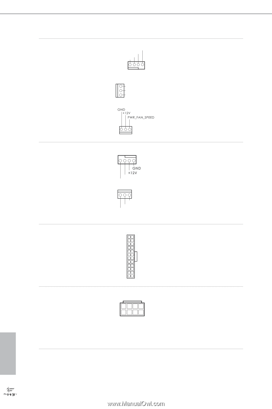
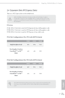
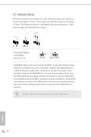
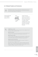
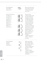
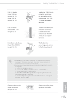
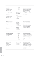
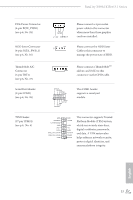
Chassis and Power Fan Connectors (4-pin CHA_FAN1) (see p.6, No. 23) (3-pin CHA_FAN2) (see p.6, No. 9) (3-pin PWR_FAN1) (see p.6, No. 31) FAN_SPEED_CONTROL FAN_SPEED +12V GND 1 234 GND FAN_VOLTAGE FAN_SPEED Please connect fan cables to the fan connectors and match the black wire to the ground pin. CHA_ FAN fan speed can be controlled through UEFI or F-Stream. CPU Fan Connectors (4-pin CPU_FAN1) (see p.6, No. 4) (3-pin CPU_FAN2) (see p.6, No. 5) ATX Power Connector (24-pin ATXPWR1) (see p.6, No. 7) ATX 12V Power Connector (8-pin ATX12V1) (see p.6, No. 2) 4 3 21 CPU_FAN_SPEED FAN_SPEED_CONTROL GND FAN_VOLTAGE FAN_SPEED his motherboard provides a 4-Pin CPU fan (Quiet Fan) connector. If you plan to connect a 3-Pin CPU fan, please connect it to Pin 1-3. 12 24 1 13 8 5 4 1 his motherboard provides a 24-pin ATX power connector. To use a 20-pin ATX power supply, please plug it along Pin 1 and Pin 13. his motherboard provides an 8-pin ATX 12V power connector. To use a 4-pin ATX power supply, please plug it along Pin 1 and Pin 5. English 22
-
 1
1 -
2
-
3
-
4
-
5
-
6
-
7
-
8
-
9
-
10
-
11
-
12
-
13
-
14
-
15
-
16
-
17
-
18
-
19
-
20
-
21
-
22
-
23
-
24
-
 25
25 -
 26
26 -
 27
27 -
 28
28 -
 29
29 -
 30
30 -
 31
31 -
 32
32 -
 33
33 -
 34
34 -
 35
35 -
36
-
37
-
38
-
39
-
40
-
41
-
42
-
43
-
44
-
45
-
46
-
47
-
48
-
49
-
50
-
51
-
52
-
53
-
54
-
55
-
56
-
57
-
58
-
59
-
60
-
61
-
62
-
63
-
64
-
65
-
66
-
67
-
68
-
69
-
70
-
71
-
72
-
73
-
74
-
75
-
76
-
77
-
78
-
79
-
80
-
81
-
82
-
83
-
84
-
85
-
86
-
87
-
88
-
89
-
90
-
91
-
92
-
93
-
94
-
95
-
96
-
97
-
98
-
99
-
100
 |
 |