ASRock Fatal1ty X99M Killer/3.1 User Manual - Page 31
Platform Module TPM system, His COM1 header
 |
View all ASRock Fatal1ty X99M Killer/3.1 manuals
Add to My Manuals
Save this manual to your list of manuals |
Page 31 highlights
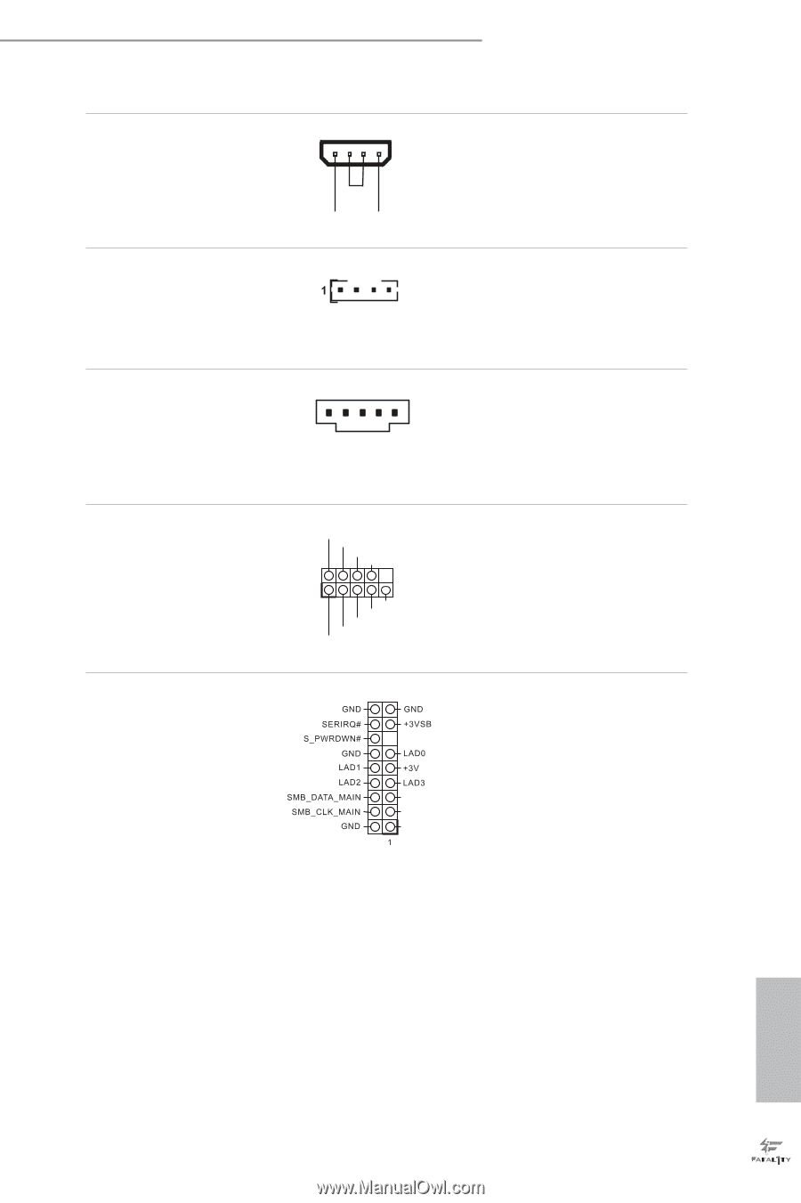
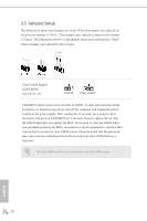
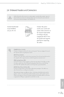
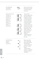
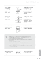
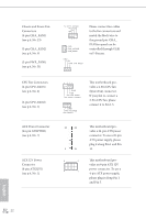
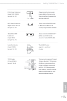
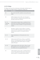
Fatal1ty X99M Killer/3.1 Series PCIe Power Connector (4-pin PCIE_PWR1) (see p.6, No. 28) HDD Saver Connector (4-pin SATA_PWR_1) (see p.6, No. 16) hunderbolt AIC Connector (5-pin TBT1) (see p.6, No. 27) Serial Port Header (9-pin COM1) (see p.6, No. 26) TPM Header (17-pin TPMS1) (see p.6, No. 6) GND +12V DETECT Please connect a 4 pin molex power cable to this connector when more than three graphics cards are installed. Please connect the HDD Saver Cable to this connector to manage the power state of HDD. Please connect a hunderboltTM add-in card (AIC) to this connector via the GPIO cable. RRXD1 DDTR#1 DDSR#1 CCTS#1 1 RRI#1 RRTS#1 GND TTXD1 DDCD#1 his COM1 header supports a serial port module. PCIRST# FRAME PCICLK his connector supports Trusted Platform Module (TPM) system, which can securely store keys, digital certiicates, passwords, and data. A TPM system also helps enhance network security, protects digital identities, and ensures platform integrity. English 23
-
 1
1 -
2
-
3
-
4
-
5
-
6
-
7
-
8
-
9
-
10
-
11
-
12
-
13
-
14
-
15
-
16
-
17
-
18
-
19
-
20
-
21
-
22
-
23
-
24
-
25
-
 26
26 -
 27
27 -
 28
28 -
 29
29 -
 30
30 -
 31
31 -
 32
32 -
 33
33 -
 34
34 -
 35
35 -
 36
36 -
37
-
38
-
39
-
40
-
41
-
42
-
43
-
44
-
45
-
46
-
47
-
48
-
49
-
50
-
51
-
52
-
53
-
54
-
55
-
56
-
57
-
58
-
59
-
60
-
61
-
62
-
63
-
64
-
65
-
66
-
67
-
68
-
69
-
70
-
71
-
72
-
73
-
74
-
75
-
76
-
77
-
78
-
79
-
80
-
81
-
82
-
83
-
84
-
85
-
86
-
87
-
88
-
89
-
90
-
91
-
92
-
93
-
94
-
95
-
96
-
97
-
98
-
99
-
100
 |
 |