ASRock G41M-LE User Manual - Page 26

ASRock G41M-LE Manual

Page 26 highlights

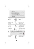
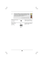
2 . 1 0 Serial A TA (SA TA) / Serial A TAII (SA TAII) Hard Disks AT (SAT AT (SAT Installation This motherboard adopts Intel® ICH7 south bridge chipset that supports Serial ATA (SATA) / Serial ATAII (SATAII) hard disks. You may install SATA / SATAII hard disks on this motherboard for internal storage devices. This section will guide you to install the SATA / SATAII hard disks. STEP 1: Install the SATA / SATAII hard disks into the drive bays of your chassis. STEP 2: Connect the SATA power cable to the SATA / SATAII hard disk. STEP 3: Connect one end of the SATA data cable to the motherboard's SATAII connector. STEP 4: Connect the other end of the SATA data cable to the SATA / SATAII hard disk. 2 . 1 1 Driver Installation Guide To install the drivers to your system, please insert the support CD to your optical drive first. Then, the drivers compatible to your system can be auto-detected and listed on the support CD driver page. Please follow the order from up to bottom side to install those required drivers. Therefore, the drivers you install can work properly. 2 . 1 2 Untied Overclocking T echnology Technology This motherboard supports Untied Overclocking Technology, which means during overclocking, FSB enjoys better margin due to fixed PCI / PCIE buses. Before you enable Untied Overclocking function, please enter "Overclock Mode" option of BIOS setup to set the selection from [Auto] to [Manual]. Therefore, CPU FSB is untied during overclocking, but PCI / PCIE buses are in the fixed mode so that FSB can operate under a more stable overclocking environment. Please refer to the warning on page 8 for the possible overclocking risk before you apply Untied Overclocking Technology. 26

  • 1
  • 2
  • 3
  • 4
  • 5
  • 6
  • 7
  • 8
  • 9
  • 10
  • 11
  • 12
  • 13
  • 14
  • 15
  • 16
  • 17
  • 18
  • 19
  • 20
  • 21
  • 22
  • 23
  • 24
  • 25
  • 26
  • 27
  • 28
  • 29
  • 30
  • 31
  • 32
  • 33
  • 34
  • 35
  • 36
  • 37
  • 38
  • 39
  • 40
  • 41
  • 42
  • 43
  • 44
  • 45
  • 46
  • 47

26
26
26
26
26
2.10
2.10
2.10
2.10
2.10 Serial A
Serial A
Serial A
Serial A
Serial ATA (SA
A (SA
A (SA
A (SA
A (SATA) / Serial A
A) / Serial A
A) / Serial A
A) / Serial A
A) / Serial ATAII (SA
AII (SA
AII (SA
AII (SA
AII (SATAII) Hard Disks
AII) Hard Disks
AII) Hard Disks
AII) Hard Disks
AII) Hard Disks
Installation
Installation
Installation
Installation
Installation
This motherboard adopts Intel
®
ICH7 south bridge chipset that supports Serial ATA
(SATA) / Serial ATAII (SATAII) hard disks. You may install SATA / SATAII hard disks on
this motherboard for internal storage devices. This section will guide you to install the
SATA / SATAII hard disks.
STEP 1:
Install the SATA / SATAII hard disks into the drive bays of your chassis.
STEP 2:
Connect the SATA power cable to the SATA / SATAII hard disk.
STEP 3:
Connect one end of the SATA data cable to the motherboard’s SATAII
connector.
STEP 4:
Connect the other end of the SATA data cable to the SATA / SATAII hard
disk.
2.11
2.11
2.11
2.11
2.11 Driver Installation Guide
Driver Installation Guide
To install the drivers to your system, please insert the support CD to your optical drive
first. Then, the drivers compatible to your system can be auto-detected and listed on
the support CD driver page. Please follow the order from up to bottom side to install
those required drivers. Therefore, the drivers you install can work properly.
2.12
2.12
2.12
2.12
2.12 Untied Overclocking T
Untied Overclocking T
Untied Overclocking Technology
echnology
echnology
echnology
echnology
This motherboard supports Untied Overclocking Technology, which means during
overclocking, FSB enjoys better margin due to fixed PCI / PCIE buses. Before you
enable Untied Overclocking function, please enter “Overclock Mode” option of BIOS
setup to set the selection from [Auto] to [Manual]. Therefore, CPU FSB is untied
during overclocking, but PCI / PCIE buses are in the fixed mode so that FSB can
operate under a more stable overclocking environment.
Please refer to the warning on page 8 for the possible overclocking risk
before you apply Untied Overclocking Technology.