ASRock H110TM-ITX User Manual - Page 23
Front Panel Audio Header, pin HD_AUDIO1
 |
View all ASRock H110TM-ITX manuals
Add to My Manuals
Save this manual to your list of manuals |
Page 23 highlights
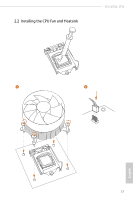
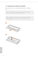
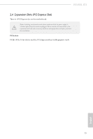
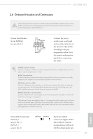
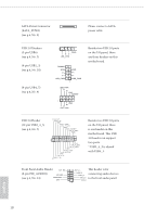
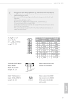
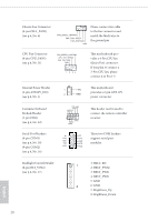
SATA Power Connector (SATA_POW1) (see p.6, No. 9) Please connect a SATA power cable. USB 2.0 Headers (5-pin USB6) (see p.6, No. 3) (9-pin USB2_3) (see p.6, No. 20) (9-pin USB4_5) (see p.6, No. 4) 1 GND P- P+ USB_PWR DUMMY GND P+ P- USB_PWR GND P+ PUSB_PWR 1 USB_PWR PP+ GND DUMMY 1 GND P+ PUSB_PWR Besides two USB 2.0 ports on the I/O panel, there are three headers on this motherboard. USB 3.0 Header (19-pin USB3_4_5) (see p.6, No. 5) IntA_P_D+ IntA_P_DGND IntA_P_SSTX+ IntA_P_SSTXGND IntA_P_SSRX+ IntA_P_SSRXVbus 1 Vbus IntA_P_SSRXIntA_P_SSRX+ GND IntA_P_SSTXIntA_P_SSTX+ GND IntA_P_DIntA_P_D+ ID Besides two USB 3.0 ports on the I/O panel, there is one header on this motherboard. This USB 3.0 header can support two ports. * USB3_4_5 is shared with USB4_5. Front Panel Audio Header OUT_RET (9-pin HD_AUDIO1) MIC_RED (see p.6, No. 24) PRESENCE# GND OUT2_L This header is for J_SENSE OUT2_R connecting audio devices MIC2_R to the front audio panel. MIC2_L 1 English 18
-
 1
1 -
2
-
3
-
4
-
5
-
6
-
7
-
8
-
9
-
10
-
11
-
12
-
13
-
14
-
15
-
16
-
17
-
 18
18 -
 19
19 -
 20
20 -
 21
21 -
 22
22 -
 23
23 -
 24
24 -
 25
25 -
 26
26 -
 27
27 -
 28
28 -
29
-
30
-
31
-
32
-
33
-
34
-
35
-
36
-
37
-
38
-
39
-
40
-
41
-
42
-
43
-
44
-
45
-
46
-
47
-
48
-
49
-
50
-
51
-
52
-
53
-
54
-
55
-
56
-
57
-
58
-
59
-
60
-
61
-
62
-
63
-
64
-
65
-
66
-
67
-
68
-
69
-
70
-
71
-
72
 |
 |