ASRock H110TM-ITX User Manual - Page 25
pin ATX19V_IN1, pin CPU_FAN1
 |
View all ASRock H110TM-ITX manuals
Add to My Manuals
Save this manual to your list of manuals |
Page 25 highlights
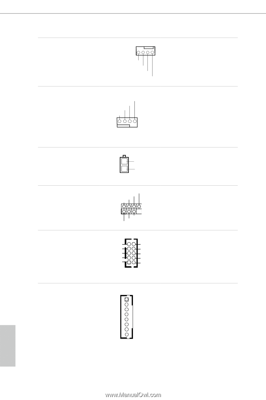
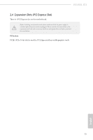
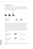
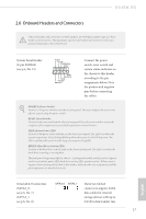
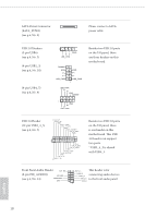
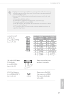
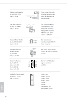
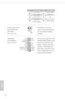
Chassis Fan Connector (4-pin CHA_FAN1) (see p.6, No. 6) FAN_SPEED_CONTROL CHA_FAN_SPEED FAN_VOLTAGE GND Please connect fan cable to the fan connector and match the black wire to the ground pin. CPU Fan Connector (4-pin CPU_FAN1) (see p.6, No. 21) FAN_SPEED_CONTROL CPU_FAN_SPEED FAN_VOLTAGE GND 1 2 34 This motherboard provides a 4-Pin CPU fan (Quiet Fan) connector. If you plan to connect a 3-Pin CPU fan, please connect it to Pin 1-3. Internal Power Header (2-pin ATX19V_IN1) (see p.6, No. 1) Consumer Infrared Module Header (7-pin CIR1) (see p.6, No. 12) Serial Port Headers (9-pin COM1) (see p.6, No. 18) (9-pin COM2) (see p.6, No. 16) This motherboard 1 +19V provides a 2-pin ATX 19V 2 GND power connector. CIR input +5VA Learn-in LED 1 +5VA IRTX GND This header can be used to connect the remote controller receiver. RI RTS GND TXD DCD 1 NC CTS DSR DTR RXD These two COM headers support serial port modules. Backlight Control Header (8-pin BLT_VOL1) (see p.6, No. 17) 1: BKLT_EN 1 2: BKLT_PWM 3: BKLT_PWR 4: BKLT_PWR 5: GND 8 6: GND 7: Brightness_Up 8: Brightness_Down English 20
-
 1
1 -
2
-
3
-
4
-
5
-
6
-
7
-
8
-
9
-
10
-
11
-
12
-
13
-
14
-
15
-
16
-
17
-
18
-
19
-
 20
20 -
 21
21 -
 22
22 -
 23
23 -
 24
24 -
 25
25 -
 26
26 -
 27
27 -
 28
28 -
 29
29 -
 30
30 -
31
-
32
-
33
-
34
-
35
-
36
-
37
-
38
-
39
-
40
-
41
-
42
-
43
-
44
-
45
-
46
-
47
-
48
-
49
-
50
-
51
-
52
-
53
-
54
-
55
-
56
-
57
-
58
-
59
-
60
-
61
-
62
-
63
-
64
-
65
-
66
-
67
-
68
-
69
-
70
-
71
-
72
 |
 |