ASRock QC5000M-ITX/PH User Manual - Page 12
I/O Panel
 |
View all ASRock QC5000M-ITX/PH manuals
Add to My Manuals
Save this manual to your list of manuals |
Page 12 highlights
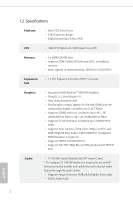
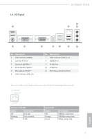
1.4 I/O Panel 1 QC5000M-ITX/PH 3 2 4 11 10 No. Description 1 USB 2.0 Ports (USB01) 2 LAN RJ-45 Port* 3 Line In (Light Blue)** 4 Front Speaker (Lime)** 5 Microphone (Pink)** 6 USB 2.0 Ports (USB_23) 9 8 7 6 5 No. Description 7 USB 3.0 Ports (USB3_0_1) 8 HDMI Port 9 D-Sub Port 10 COM Port 11 PS/2 Mouse/Keyboard Port * here are two LEDs on each LAN port. Please refer to the table below for the LAN port LED indications. ACT/LINK LED SPEED LED LAN Port Activity / Link LED Status Description Of Blinking On No Link Data Activity Link Speed LED Status Of Orange Green Description 10Mbps connection 100Mbps connection 1Gbps connection 7 English
-
 1
1 -
2
-
3
-
4
-
5
-
6
-
 7
7 -
 8
8 -
 9
9 -
 10
10 -
 11
11 -
 12
12 -
 13
13 -
 14
14 -
 15
15 -
 16
16 -
 17
17 -
18
-
19
-
20
-
21
-
22
-
23
-
24
-
25
-
26
-
27
-
28
-
29
-
30
-
31
-
32
-
33
-
34
-
35
-
36
-
37
-
38
-
39
-
40
-
41
-
42
-
43
-
44
-
45
-
46
-
47
-
48
-
49
-
50
-
51
-
52
-
53
-
54
 |
 |

QC5000M-ITX/PH
7
English
1.4
I/O Panel
No.
Description
No.
Description
1
USB 2.0 Ports (USB01)
7
USB 3.0 Ports (USB3_0_1)
2
LAN RJ-45 Port*
8
³DMI Port
3
Line In (Light Blue)**
9
D-Sub Port
4
Front Speaker (Lime)**
10
COM Port
5
Microphone (Pink)**
11
PS/2 Mouse/Keyboard Port
6
USB 2.0 Ports (USB_23)
* Here are two LEDs on each LAN port. Please refer to the table below for the LAN port LED indications.
Activity / Link LED
Speed LED
Status
Description
Status
Description
Oµ
No Link
Oµ
10Mbps connection
Blinking
Data Activity
Orange
100Mbps connection
On
Link
Green
1Gbps connection
ACT/LINK LED
SPEED LED
LAN Port
1
2
6
7
11
8
9
10
4
5
3