ASRock QC5000M-ITX/PH User Manual - Page 21
pin CPU_FAN1
 |
View all ASRock QC5000M-ITX/PH manuals
Add to My Manuals
Save this manual to your list of manuals |
Page 21 highlights
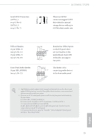
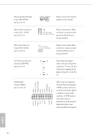
Chassis Speaker Header (4-pin SPEAKER1) (see p.5, No. 8) Chassis Fan Connector (4-pin CHA_FAN1) (see p.5, No. 3) CPU Fan Connector (3-pin CPU_FAN1) (see p.5, No. 9) ATX Power Connector (24-pin ATXPWR1) (see p.5, No. 4) TPM Header (17-pin TPMS1) (see p.5, No. 12) 1 PCICLK FRAM E PCIRST # LAD3 +3V LAD0 +3VS B GN D GN D SMB_CLK_MAIN SMB_DATA_MAIN LAD2 LAD1 GN D S_PWRDWN # SERIRQ # GND DUMMY SPEAKER 1 +5V DUMMY Please connect the chassis speaker to this header. GND +12V CHA_FAN_SPEED FAN_SPEED_CONTROL Please connect fan cables to the fan connectors and match the black wire to the ground pin. GND FAN_VOLTAGE CPU_FAN_SPEED Please connect fan cables to the fan connectors and match the black wire to the ground pin. 12 24 1 13 his motherboard provides a 24-pin ATX power connector. To use a 20-pin ATX power supply, please plug it along Pin 1 and Pin 13. his connector supports Trusted Platform Module (TPM) system, which can securely store keys, digital certiicates, passwords, and data. A TPM system also helps enhance network security, protects digital identities, and ensures platform integrity. English 16
-
 1
1 -
2
-
3
-
4
-
5
-
6
-
7
-
8
-
9
-
10
-
11
-
12
-
13
-
14
-
15
-
 16
16 -
 17
17 -
 18
18 -
 19
19 -
 20
20 -
 21
21 -
 22
22 -
 23
23 -
 24
24 -
 25
25 -
 26
26 -
27
-
28
-
29
-
30
-
31
-
32
-
33
-
34
-
35
-
36
-
37
-
38
-
39
-
40
-
41
-
42
-
43
-
44
-
45
-
46
-
47
-
48
-
49
-
50
-
51
-
52
-
53
-
54
 |
 |
