Acer Altos R701 Altos R700 Chassis Subassembly - Page 14
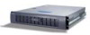
Chassis Back I/O Ports and Features
 |
View all Acer Altos R701 manuals
Add to My Manuals
Save this manual to your list of manuals |
Page 14 highlights
6 1 Chassis Description Label D E F Description Flex bay (optional DVD/CD-ROM drive/FDD module shown installed) Front panel indicator lights Tape drive bay (tape drive not included) Chassis Back I/O Ports and Features Label A B C D E F G H I Description PCI card bracket (low profile) RJ45 NIC 2 connector Green Status LED/ Yellow Status LED Serial A port mounting hole (cable not provided) PCI card bracket (full-height) AC power input (primary) AC power input (redundant) Power supply module, redundant (system accessory) Power supply module, primary USB connector 2
-
 1
1 -
2
-
3
-
4
-
5
-
6
-
7
-
8
-
 9
9 -
 10
10 -
 11
11 -
 12
12 -
 13
13 -
 14
14 -
 15
15 -
 16
16 -
 17
17 -
 18
18 -
 19
19 -
20
-
21
-
22
-
23
-
24
-
25
-
26
-
27
-
28
-
29
-
30
-
31
-
32
-
33
-
34
-
35
-
36
-
37
-
38
-
39
-
40
-
41
-
42
-
43
-
44
-
45
-
46
-
47
-
48
-
49
-
50
-
51
-
52
-
53
-
54
-
55
-
56
-
57
-
58
-
59
-
60
-
61
-
62
-
63
-
64
-
65
-
66
-
67
-
68
-
69
-
70
-
71
-
72
-
73
-
74
-
75
-
76
-
77
-
78
-
79
-
80
 |
 |

1 Chassis Description
6
Chassis Back I/O Ports and Features
D
Flex bay (optional DVD/CD-ROM drive/FDD
module shown installed)
E
Front panel indicator lights
F
Tape drive bay (tape drive not included)
Label
Description
A
PCI card bracket (low profile)
B
RJ45 NIC 2 connector Green Status LED/
Yellow Status LED
C
Serial A port mounting hole (cable not
provided)
D
PCI card bracket (full-height)
E
AC power input (primary)
F
AC power input (redundant)
G
Power supply module, redundant (system
accessory)
H
Power supply module, primary
I
USB connector 2
Label
Description