Acer Chromebook Spin 713 CP713-3W Lifecycle Extension Guide - Page 21
USB Board Removal
 |
View all Acer Chromebook Spin 713 CP713-3W manuals
Add to My Manuals
Save this manual to your list of manuals |
Page 21 highlights
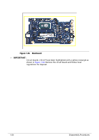
3. Close the top assembly and lift the left side of LCD hinge until it is fully extended (Figure 1-25). Figure 1-25. USB Board Removal 4. Disconnect the 40-pin USB board FFC (B) from the mainboard and USB board connectors (Figure 1-26). 5. Disconnect the G-sensor cable from the USB board connector (C) (Figure 1-26). 6. Disconnect the fingerprint cable from the USB board connector (D). Then unroute the WLAN antennas cables from the cable guides (Figure 1-26). 7. Remove two (2) screws (E) securing the USB board in place (Figure 1-26). C B E D Figure 1-26. USB Board Removal Disassembly Procedures 1-19
-
 1
1 -
2
-
3
-
4
-
5
-
6
-
7
-
8
-
9
-
10
-
11
-
12
-
13
-
14
-
15
-
 16
16 -
 17
17 -
 18
18 -
 19
19 -
 20
20 -
 21
21 -
 22
22 -
 23
23 -
 24
24 -
 25
25 -
 26
26 -
27
-
28
-
29
-
30
-
31
-
32
-
33
-
34
-
35
-
36
-
37
 |
 |

Disassembly Procedures
1-19
3.
Close the top assembly and lift the left side of LCD hinge until it is fully extended
(
Figure 1-25
).
Figure 1-25.
USB Board Removal
4.
Disconnect the 40-pin USB board FFC (B) from the mainboard and USB board
connectors (
Figure 1-26
).
5.
Disconnect the G-sensor cable from the USB board connector (C) (
Figure 1-26
).
6.
Disconnect the fingerprint cable from the USB board connector (D). Then unroute the
WLAN antennas cables from the cable guides (
Figure 1-26
).
7.
Remove two (2) screws (E) securing the USB board in place (
Figure 1-26
).
Figure 1-26.
USB Board Removal
B
C
D
E