Acer Chromebook Spin 713 CP713-3W Lifecycle Extension Guide - Page 35
Exploded Diagrams, LCD Module, Camera Module, LCD Hinge L, eDP Cable, LCD Cover,
 |
View all Acer Chromebook Spin 713 CP713-3W manuals
Add to My Manuals
Save this manual to your list of manuals |
Page 35 highlights
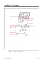
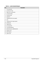
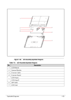
1 2 5 3 4 6 7 Figure 1-42. LCD Assembly Exploded Diagram Table 1-3. LCD Assembly Exploded Diagram No. Description 1 LCD Module 2 Camera Module 3 G-sensor Cable 4 G-sensor Board LCD Hinge L 5 LCD Hinge R 6 eDP Cable 7 LCD Cover Exploded Diagrams 1-33
-
 1
1 -
2
-
3
-
4
-
5
-
6
-
7
-
8
-
9
-
10
-
11
-
12
-
13
-
14
-
15
-
16
-
17
-
18
-
19
-
20
-
21
-
22
-
23
-
24
-
25
-
26
-
27
-
28
-
29
-
 30
30 -
 31
31 -
 32
32 -
 33
33 -
 34
34 -
 35
35 -
 36
36 -
 37
37
 |
 |

Exploded Diagrams
1-33
Figure 1-42.
LCD Assembly Exploded Diagram
Table 1-3.
LCD Assembly Exploded Diagram
No.
Description
1
LCD Module
2
Camera Module
3
G-sensor Cable
4
G-sensor Board
5
LCD Hinge L
LCD Hinge R
6
eDP Cable
7
LCD Cover
5
6
7
2
3
4
1