Acer RC271U User Manual non-type c - Page 16
Display Data Channel (DDC), Connector pin assignment, pin color display signal cable
 |
View all Acer RC271U manuals
Add to My Manuals
Save this manual to your list of manuals |
Page 16 highlights
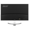
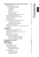
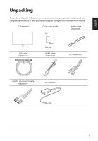
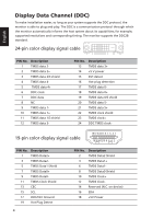
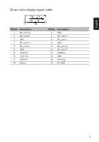
English Display Data Channel (DDC) To make installation easier, so long as your system supports the DDC protocol, the monitor is able to plug-and-play. The DDC is a communication protocol through which the monitor automatically informs the host system about its capabilities; for example, supported resolutions and corresponding timing. The monitor supports the DDC2B standard. 24-pin color display signal cable PIN No. Description 1 TMDS data 2- 2 TMDS data 2+ 3 TMDS data 2/4 shield 4 TMDS data 4- 5 TMDS data 4+ 6 DDC clock 7 DDC data 8 NC 9 TMDS data 1- 10 TMDS data 1+ 11 TMDS data 1/3 shield 12 TMDS data 3- PIN No. Description 13 TMDS data 3+ 14 +5 V power 15 DVI detect 16 Hot-plug detection 17 TMDS data 018 TMDS data 0+ 19 TMDS data 0/5 shield 20 TMDS data 521 TMDS data 5+ 22 TMDS clock shield 23 TMDS clock+ 24 DDC TMDS clock- 19-pin color display signal cable 1917151311 9 7 5 3 1 18161412 10 8 6 4 2 PIN No. Description 1 TMDS Data2+ 3 TMDS Data2- 5 TMDS Data1 Shield 7 TMDS Data0+ 9 TMDS Data0- 11 TMDS Clock Shield 13 CEC 15 SCL 17 DDC/CEC Ground 19 Hot Plug Detect 4 PIN No. Description 2 TMDS Data2 Shield 4 TMDS Data1+ 6 TMDS Data1- 8 TMDS Data0 Shield 10 TMDS Clock+ 12 TMDS Clock- 14 Reserved (N.C. on device) 16 SDA 18 +5V Power
-
 1
1 -
2
-
3
-
4
-
5
-
6
-
7
-
8
-
9
-
10
-
 11
11 -
 12
12 -
 13
13 -
 14
14 -
 15
15 -
 16
16 -
 17
17 -
 18
18 -
 19
19 -
 20
20 -
 21
21 -
22
-
23
-
24
-
25
-
26
-
27
-
28
-
29
-
30
 |
 |