Acer RC271U User Manual type c - Page 17
pin color display signal cable, pin color display signal cable
 |
View all Acer RC271U manuals
Add to My Manuals
Save this manual to your list of manuals |
Page 17 highlights
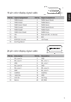
English 19-pin color display signal cable PIN No. Signal Assignment 1 TMDS Data2+ 3 TMDS Data2- 5 TMDS Data1 Shield 7 TMDS Data0+ 9 TMDS Data0- 11 TMDS Clock Shield 13 CEC 15 SCL 17 EDID/CEC Ground 19 Hot Plug Detect PIN No. Signal Assignment 2 TMDS Data2 Shield 4 TMDS Data1+ 6 TMDS Data1- 8 TMDS Data0 Shield 10 TMDS Clock+ 12 TMDS Clock- 14 Reserved (N.C. on device) 16 SDA 18 +5V Power 20-pin color display signal cable PIN No. Description 1 ML_Lane 0+ 3 ML_Lane 0- 5 GND 7 ML_Lane 2+ 9 ML_Lane 2- 11 GND 13 CONFIG1 15 AUX CH+ 17 AUX CH- 19 Return PIN No. Description 2 GND 4 ML_Lane 1+ 6 ML_Lane 1- 8 GND 10 ML_Lane 3+ 12 ML_Lane 3- 14 CONFIG2 16 GND 18 Hot Plug 20 DP_PWR 5
-
 1
1 -
2
-
3
-
4
-
5
-
6
-
7
-
8
-
9
-
10
-
11
-
 12
12 -
 13
13 -
 14
14 -
 15
15 -
 16
16 -
 17
17 -
 18
18 -
 19
19 -
 20
20 -
 21
21 -
 22
22 -
23
-
24
-
25
-
26
-
27
-
28
-
29
-
30
 |
 |

5
English
19-pin color display signal cable
PIN No.
Signal Assignment
PIN No.
Signal Assignment
1
TMDS Data2+
2
TMDS Data2 Shield
3
TMDS Data2-
4
TMDS Data1+
5
TMDS Data1 Shield
6
TMDS Data1-
7
TMDS Data0+
8
TMDS Data0 Shield
9
TMDS Data0-
10
TMDS Clock+
11
TMDS Clock Shield
12
TMDS Clock-
13
CEC
14
Reserved (N.C. on device)
15
SCL
16
SDA
17
EDID/CEC Ground
18
+5V Power
19
Hot Plug Detect
20-pin color display signal cable
PIN No.
Description
PIN No.
Description
1
ML_Lane 0+
2
GND
3
ML_Lane 0-
4
ML_Lane 1+
5
GND
6
ML_Lane 1-
7
ML_Lane 2+
8
GND
9
ML_Lane 2-
10
ML_Lane 3+
11
GND
12
ML_Lane 3-
13
CONFIG1
14
CONFIG2
15
AUX CH+
16
GND
17
AUX CH-
18
Hot Plug
19
Return
20
DP_PWR