Acer TravelMate P6 Lifecycle Extension Guide
Acer TravelMate P6 Manual
 |
View all Acer TravelMate P6 manuals
Add to My Manuals
Save this manual to your list of manuals |
Acer TravelMate P6 manual content summary:
- Acer TravelMate P6 | Lifecycle Extension Guide - Page 1
TravelMate P614-52/P614P-52/614RN-52 LIFECYCLE EXTENSION GUIDE - Acer TravelMate P6 | Lifecycle Extension Guide - Page 2
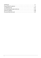
Self-Repair 1-1 Disassembly Procedures 1-3 Troubleshooting 1-41 FRU (Field Replaceable Unit) List 1-42 Software Update 1-46 Personal Data Removal 1-47 i - Acer TravelMate P6 | Lifecycle Extension Guide - Page 3
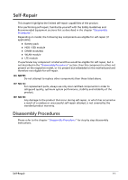
components than those listed above. NOTE: NOTE: For replacement parts, always use only Acer certified components in order to safeguard quality, optimum system performance, stability and reliability of the chapter "Disassembly Procedures" for step by step disassembly instructions. Self-Repair 1-1 - Acer TravelMate P6 | Lifecycle Extension Guide - Page 4
"Recovery" which is available in the User Manual of the product. NOTE: NOTE: In the event of not being able to create a Factory Default recovery media, it is possible to obtain a copy of the recovery media through Acer Customer Service (http://www.acer.com/support) This is not a free of charge - Acer TravelMate P6 | Lifecycle Extension Guide - Page 5
will be voided. Before you start any of the procedures in this chapter, make sure to read the following safety guidelines and the respective instructions within the chapter. CAUTION! Turn off your computer and disconnect all power sources before opening the computer cover or panels. To avoid - Acer TravelMate P6 | Lifecycle Extension Guide - Page 6
WEEE Annex VII Component 0 These components are classified as requiring selective treatment: Battery SSD Module RTC Battery 5G Module USB Board Mainboard Touchpad LCD Panel 1-4 Disassembly Procedures - Acer TravelMate P6 | Lifecycle Extension Guide - Page 7
Pre-disassembly Instructions 0 Do the following prior to starting any maintenance procedures: 1. Place the system on a stable work surface. 2. Remove AC adapter (A) from the system and peripherals (Figure 1-1). 3. - Acer TravelMate P6 | Lifecycle Extension Guide - Page 8
NOTE: NOTE: Make sure the system is completely powered off. 1-6 Disassembly Procedures - Acer TravelMate P6 | Lifecycle Extension Guide - Page 9
Base Cover Removal 0 1. Remove eleven (11) screws from the base cover (Figure 1-3). Figure 1-3. Base Cover Removal 2. Carefully pry up the base cover starting from the bottom side to release the latches. Then continue releasing the remaining latches on the left and right sides (Figure 1-4). Figure - Acer TravelMate P6 | Lifecycle Extension Guide - Page 10
3. Grasp and remove the base cover from the system (Figure 1-5). Figure 1-5. Base Cover Removal 1-8 Disassembly Procedures - Acer TravelMate P6 | Lifecycle Extension Guide - Page 11
Battery Pack Removal 0 Prerequisite: Base Cover Removal 1. Find the battery pack (A) in the system (Figure 1-6). 2. Detach the acetate tape (B) from the battery cable connector (Figure 1-6). B A Figure 1-6. Battery Pack Removal 3. Disconnect the battery cable from the mainboard connector (C) (Figure - Acer TravelMate P6 | Lifecycle Extension Guide - Page 12
4. Remove the battery pack from the system (Figure 1-8). WEEE Annex VII Component: Battery Figure 1-8. Battery Pack Removal + IMPORTANT: Follow local regulations for battery disposal. 1-10 Disassembly Procedures - Acer TravelMate P6 | Lifecycle Extension Guide - Page 13
SSD Module Removal 0 Prerequisite: Battery Pack Removal 1. Remove one (1) screw securing the SSD module (A) in place (Figure 1-9). A Figure 1-9. SSD Module Removal 2. Remove the SSD module from the mainboard connector (B) (Figure 1-10). WEEE Annex VII Component: SSD B Figure 1-10. SDD Module - Acer TravelMate P6 | Lifecycle Extension Guide - Page 14
RTC Battery Removal 0 Prerequisite: Battery Pack Removal 1. Detach the RTC battery cable from the mainboard connector (A) (Figure 1-11). 2. Pry to detach the adhesive tape underneath the RTC battery (Figure 1-11). 3. Remove the RTC battery from the top assembly (Figure 1-11). WEEE Annex VII - Acer TravelMate P6 | Lifecycle Extension Guide - Page 15
5G Module Removal (5G SKU) 0 Prerequisite: Ensure that the Heatsink & Fan (5G SKU) have been disassembled prior removing the 5G module. 1. Disconnect the 5G antenna cables from the 5G module connectors (Figure 1-12). 2. Remove one (1) screw securing the 5G module in place (Figure 1-12). Figure 1-12 - Acer TravelMate P6 | Lifecycle Extension Guide - Page 16
USB Board Removal (5G SKU) 0 Prerequisite: Ensure that the Heatsink & Fan (5G SKU) have been disassembled prior removing the USB board (5G SKU). 1. Remove two (2) screw securing the right side LCD hinge in place (Figure 1-14). Figure 1-14. USB Board Removal 2. Slightly rotate the top assembly - Acer TravelMate P6 | Lifecycle Extension Guide - Page 17
3. Lift the right LCD hinge upwards until it is fully open (Figure 1-16). Figure 1-16. USB Board Removal 4. Disconnect the USB board FFC from the USB board connector (A) and mainboard connector (B) (Figure 1-17). 5. Disconnect the fingerprint board FFC from the USB board connector (C) (Figure 1-17 - Acer TravelMate P6 | Lifecycle Extension Guide - Page 18
7. Slightly lift the USB board to release it from the guide pin (D) and then slide the USB board to release its connectors from the slots on the top assembly (Figure 1-18). D WEEE Annex VII Component: USB Board Figure 1-18. USB Board Removal 1-16 Disassembly Procedures - Acer TravelMate P6 | Lifecycle Extension Guide - Page 19
USB Board Removal (WiFi SKU) 0 Prerequisite: Ensure that the Heatsink & Fan (WiFi SKU) have been disassembled prior removing the USB board (WiFi SKU). 1. Remove two (2) screw securing the LCD hinge in place (Figure 1-19). Figure 1-19. USB Board Removal 2. Slightly rotate the top assembly upwards - Acer TravelMate P6 | Lifecycle Extension Guide - Page 20
3. Lift the right LCD hinge upwards until it is fully open (Figure 1-21). Figure 1-21. USB Board Removal 4. Disconnect the USB board FFC from the USB board connector (A) and mainboard connector (B) (Figure 1-22). 5. Disconnect the fingerprint board FFC from the USB board connector (C) (Figure 1-22 - Acer TravelMate P6 | Lifecycle Extension Guide - Page 21
8. Slightly lift the USB board to release it from the guide pin (E) and then slide the USB board to release its connectors from the slots on the top assembly (Figure 1-23). E WEEE Annex VII Component: USB Board Figure 1-23. USB Board Removal Disassembly Procedures 1-19 - Acer TravelMate P6 | Lifecycle Extension Guide - Page 22
LCD Module Removal 0 Prerequisite: Ensure that the Heatsink & Fan (5G SKU) and Heatsink & Fan (WiFi SKU) have been disassembled prior removing the LCD module. 1. Detach the mylar from the top assembly (Figure 1-24). Figure 1-24. LCD Module Removal 1-20 Disassembly Procedures - Acer TravelMate P6 | Lifecycle Extension Guide - Page 23
2. Disconnect the eDP cable from the mainboard connector (A) and unroute from the cable guides (Figure 1-25). 3. Disconnect the LCD cable from the mainboard connector (B) and unroute from the cable guides (Figure 1-25). 4. Remove four (4) screws securing the LCD hinges in place (Figure 1-25). A B - Acer TravelMate P6 | Lifecycle Extension Guide - Page 24
6. Lift the LCD hinges upwards until they are fully open (Figure 1-27). Figure 1-27. LCD Module Removal 7. Lift the LCD module away from the top assembly (Figure 1-28). Figure 1-28. LCD Module Removal ! CAUTION: Make sure all cables and antennas are moved away from the device to avoid damage - Acer TravelMate P6 | Lifecycle Extension Guide - Page 25
Mainboard Removal 0 Prerequisite: SSD Module Removal and 5G Module Removal (5G SKU) 1. Detach the mylar from the top assembly (Figure 1-29). 2. Remove two (2) screws securing the LCD hinge in place (Figure 1-29). Figure 1-29. Mainboard Removal Disassembly Procedures 1-23 - Acer TravelMate P6 | Lifecycle Extension Guide - Page 26
3. Lift the top assembly until it is fully open (Figure 1-30). Figure 1-30. Mainboard Removal 4. Lift the LCD hinge until it is fully extended (Figure 1-31). Figure 1-31. Mainboard Removal 5. Disconnect the right speaker cable from the mainboard connector (A) (Figure 1-32). 6. Disconnect the eDP - Acer TravelMate P6 | Lifecycle Extension Guide - Page 27
11. Disconnect the keyboard backlight FFC from the mainboard connector (G) (Figure 1-32). 12. Disconnect the NFC board FFC from the mainboard connector (H) (Figure 1-32). 13. Disconnect the sensor board FFC from the mainboard connector (I) (Figure 1-32). 14. Pry to detach the adhesive tape - Acer TravelMate P6 | Lifecycle Extension Guide - Page 28
18. Remove six (6) screws securing the mainboard in place (Figure 1-33). Figure 1-33. Mainboard Removal 19. Slightly lift and then slide the mainboard to release its connectors from the slots on the top assembly and from the tabs (N) (Figure 1-34). N N WEEE Annex VII Component: Mainboard Figure 1- - Acer TravelMate P6 | Lifecycle Extension Guide - Page 29
! CAUTION: USB board FFC (Flexible Flat Circuit), touchpad FFC, and keyboard FPC (Flexible Printed Circuit) can be damaged if removed while the mainboard connectors are locked. Figure 1-35. Mainboard + IMPORTANT: Circuit board >10 cm² has been highlighted with a yellow rectangle as shown in Figure - Acer TravelMate P6 | Lifecycle Extension Guide - Page 30
Touchpad Module Removal 0 Prerequisite: Mainboard Removal 1. Disconnect the NFC module cable from the NFC board connector (A) and detach from the top assembly and touchpad module (Figure 1-36). 2. Remove the NFC module (B) from the system (Figure 1-36). 3. Disconnect the touchpad FFC from the - Acer TravelMate P6 | Lifecycle Extension Guide - Page 31
. Touchpad Module Removal 5. With both hands placed underneath the touchpad module, push the touchpad module slightly to disengage it from the guide pins (D), and then remove the touchpad module (E) from the top assembly (Figure 1-38). D D E WEEE Annex VII Component: Touchpad Module Figure 1-38 - Acer TravelMate P6 | Lifecycle Extension Guide - Page 32
LCD Bezel Removal (Clamshell SKU Only) 0 Prerequisite: LCD Module Removal 1. Pry the LCD bezel from the bottom side to release latches (Figure 1-39). Figure 1-39. LCD Bezel Removal 2. Continue along the right side of the bezel (Figure 1-40). Figure 1-40. LCD Bezel Removal 1-30 Disassembly - Acer TravelMate P6 | Lifecycle Extension Guide - Page 33
3. Pry the LCD bezel from the left side to release latches (Figure 1-41). Figure 1-41. LCD Bezel Removal 4. Continue along the upper side of the bezel until all the latches have been released (Figure 1-42). Then lift and remove the bezel from LCD module. Figure 1-42. LCD Bezel Removal Disassembly - Acer TravelMate P6 | Lifecycle Extension Guide - Page 34
Removal (Clamshell SKU Only) 1. Remove the rubber from the LCD cap and then remove the eDP cable from the LCD cap and from the cable guides on the LCD cover (Figure 1-43). Figure 1-43. LCD Panel & eDP Cable Removal 1-32 Disassembly Procedures - Acer TravelMate P6 | Lifecycle Extension Guide - Page 35
2. Pry slightly to access the double-sided mounting tape (A) underneath the LCD panel (B). Then pull to detach the double-sided mounting tape from the LCD cover. Repeat the same procedure to remove the double-sided mounting tape on another side of the LCD panel (Figure 1-44). WEEE Annex VII - Acer TravelMate P6 | Lifecycle Extension Guide - Page 36
4. Lift the latch securing the eDP cable (Figure 1-46). Figure 1-46. LCD Panel & eDP Cable Removal 5. Disconnect the eDP cable from the LCD panel connector (D) (Figure 1-47). D Figure 1-47. LCD Panel & eDP Cable Removal 6. Remove the LCD panel from the LCD cover. 1-34 Disassembly Procedures - Acer TravelMate P6 | Lifecycle Extension Guide - Page 37
LCD Panel & eDP Cable Removal (Convertible) 0 Prerequisite: LCD Module Removal 1. Rotate the LCD hinges all the way backwards toward the LCD cover (Figure 1-48). Figure 1-48. LCD Panel & eDP Cable Removal 2. Pry the LCD panel from the bottom side to release the latches as shown in Figure 1-49. - Acer TravelMate P6 | Lifecycle Extension Guide - Page 38
3. Pry slightly to access the double-sided mounting tape (A) underneath the LCD panel (B). Then pull to detach the double-sided mounting tape from the LCD cover. Repeat the same procedure to remove the double-sided mounting tape on another side of the LCD panel (Figure 1-50). WEEE Annex VII - Acer TravelMate P6 | Lifecycle Extension Guide - Page 39
5. Rotate the LCD hinges all the way up (Figure 1-52). Figure 1-52. LCD Panel & eDP Cable Removal 6. Release the eDP cable from the LCD cap (Figure 1-53). 7. Then lift and remove the LCD panel from LCD cover (Figure 1-53). Figure 1-53. LCD Panel & eDP Cable Removal Disassembly Procedures 1-37 - Acer TravelMate P6 | Lifecycle Extension Guide - Page 40
8. Carefully turn the LCD panel over so that the display panel is facing down on a flat surface. 9. Disconnect the eDP cable from the LCD panel connector (C) (Figure 1-54). 10. Then detach the eDP cable from the LCD panel (Figure 1-54). C Figure 1-54. LCD Panel & eDP Cable Removal 11. Detach the - Acer TravelMate P6 | Lifecycle Extension Guide - Page 41
12. Lift the latch securing the eDP cable (Figure 1-56). Figure 1-56. LCD Panel & eDP Cable Removal 13. Disconnect the eDP cable from the LCD panel connector (D) (Figure 1-57). D Figure 1-57. LCD Panel & eDP Cable Removal 14. Remove the LCD panel from the LCD cover. Disassembly Procedures 1-39 - Acer TravelMate P6 | Lifecycle Extension Guide - Page 42
Top Assembly Removal (Keyboard Removal) 0 Prerequisite: Ensure that the NFC Module, WLAN Antenna (WiFi SKU), 5G / WLAN Antenna Left and Right (5G SKU), Speaker Module, Fingerprint Module, and Stylus Holder (Optional) have been disassembled prior removing the top assembly. NOTE: NOTE: The keyboard is - Acer TravelMate P6 | Lifecycle Extension Guide - Page 43
attempt to open the computer yourself; contact your dealer or authorized service center for assistance. Troubleshooting tips 0 This computer incorporates an advanced design that delivers on-screen error message reports to help you solve problems. If the system reports an error message or an error - Acer TravelMate P6 | Lifecycle Extension Guide - Page 44
FRU (Field Replaceable Unit) List Please contact your local service center to find out how to obtain the part or replace your device. 1-42 FRU (Field Replaceable Unit) List - Acer TravelMate P6 | Lifecycle Extension Guide - Page 45
Exploded Diagrams 0 1 2 4 5 3 6 7 4 9 10 8 11 12 13 14 16 15 18 17 19 20 21 22 22 Figure 1-59. System Exploded Diagram Table 1-2. System Exploded Diagram No. 1 LOWER CASE 2 FAN (for WIFI SKU) 3 HEATSINK 4 RIGHT SPEAKER LEFT SPEAKER 5 LTE MODULE 6 I/O BOARD 7 I/O BOARD FFC 8 - Acer TravelMate P6 | Lifecycle Extension Guide - Page 46
Table 1-2. System Exploded Diagram No. Description 9 NFC BOARD FFC 10 ADHESIVE TAPE FOR NFC BOARD 11 NFC MODULE 12 GMR SENSOR BOARD FFC 13 GMR SENSOR BOARD 14 SSD 15 TOUCHPAD 16 FINGERPRINT BOARD FFC 17 BATTERY 18 FINGERPRINT BOARD 19 TOUCHPAD FFC 20 FINGERPRINT BOARD BRACKET 21 UPPER - Acer TravelMate P6 | Lifecycle Extension Guide - Page 47
BOARD 8 TOF SENSOR BOARD 9 CAMERA CABLE 10 LCD COVER 11 LEFT HINGE WITH RUBBER RIGHT HINGE WITH RUBBER FRU (Field Replaceable Unit) List 2 3 7 8 9 10 11 Acer Part No. 60.VSYN7.003 KL.14005.058 50.VSYN7.008 47.VSYN7.003 KS.FHD06.003 55.VSYN7.003 47.VSYN7.004 55.VSYN7 - Acer TravelMate P6 | Lifecycle Extension Guide - Page 48
Software Update Updating your software 0 Please visit http://go.acer.com/?id=17883 1-46 Software Update - Acer TravelMate P6 | Lifecycle Extension Guide - Page 49
hold down the Shift key while you select the Power icon > Restart in the lower-right corner of the screen. After your computer restarts, select Troubleshoot > Reset this PC. Option 3: Select Start , then press and hold down the Shift key while you select the Power icon > Restart to restart your
-
 1
1 -
 2
2 -
 3
3 -
 4
4 -
 5
5 -
 6
6 -
 7
7 -
8
-
9
-
10
-
11
-
12
-
13
-
14
-
15
-
16
-
17
-
18
-
19
-
20
-
21
-
22
-
23
-
24
-
25
-
26
-
27
-
28
-
29
-
30
-
31
-
32
-
33
-
34
-
35
-
36
-
37
-
38
-
39
-
40
-
41
-
42
-
43
-
44
-
45
-
46
-
47
-
48
-
49
 |
 |

TravelMate P614-52/P614P-52/614RN-52
LIFECYCLE EXTENSION
GUIDE