Adaptec AHA-1522B Installation Guide - Page 2
Hardware, Installation
 |
UPC - 760884126073
View all Adaptec AHA-1522B manuals
Add to My Manuals
Save this manual to your list of manuals |
Page 2 highlights
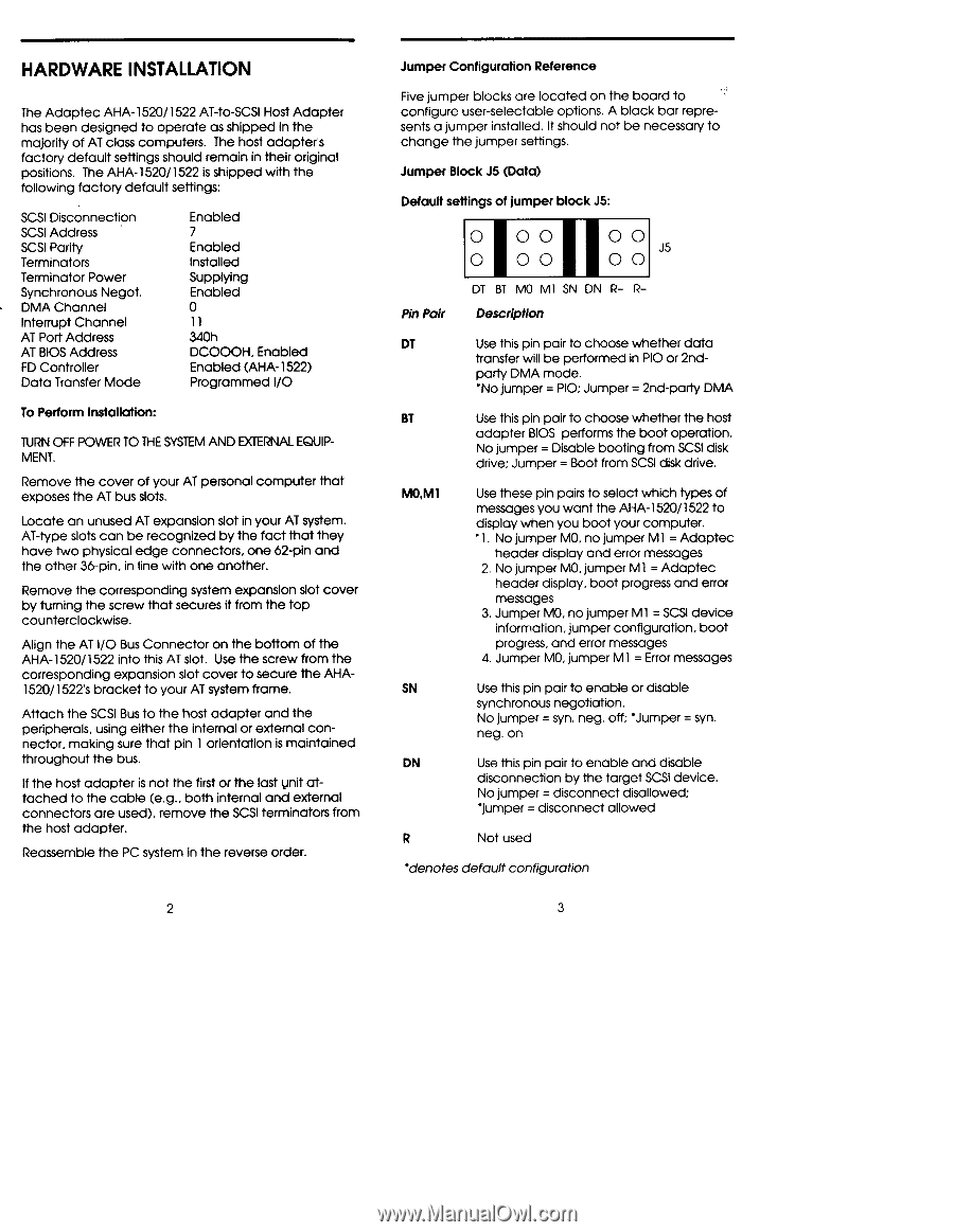
HARDWARE INSTALLATION The Adaptec AHA-1520/1522 AT-to-SCSI Host Adapter has been designed to operate as shipped in the majority of AT class computers. The host adapters factory default settings should remain in their original positions. The AHA-1520/1522 is shipped with the following factory default settings: SCSI Disconnection SCSI Address SCSI Parity Terminators Terminator Power Synchronous Negot. DMA Channel Interrupt Channel AT Port Address AT BIOS Address FD Controller Data Transfer Mode Enabled 7 Enabled Installed Supplying Enabled 0 11 340h DCOOOH, Enabled Enabled (AHA-1522) Programmed I/O To Perform Installation: TURN OFF POWER TO THE SYSTEM AND EXTERNAL EQUIPMENT. Remove the cover of your AT personal computer that exposes the AT bus slots. Locate an unused AT expansion slot in your AT system. AT-type slots can be recognized by the fact that they have two physical edge connectors, one 62-pin and the other 36-pin, in line with one another. Remove the corresponding system expansion slot cover by turning the screw that secures it from the top counterclockwise. Align the AT I/O Bus Connector on the bottom of the AHA-1520/1522 into this AT slot. Use the screw from the corresponding expansion slot cover to secure the AHA1520/1522's bracket to your AT system frame. Attach the SCSI Bus to the host adapter and the peripherals, using either the internal or external connector, making sure that pin 1 orientation is maintained throughout the bus. If the host adapter is not the first or the last unit attached to the cable (e.g., both internal and external connectors are used), remove the SCSI terminators from the host adapter. Reassemble the PC system in the reverse order. Jumper Configuration Reference Five jumper blocks are located on the board to configure user-selectable options. A black bar represents a jumper installed. It should not be necessary to change the jumper settings. Jumper Block J5 (Data) Default settings of jumper block J5: 0 00 0 00 0 0 J5 0 0 Pin Pair DT BT MO MI SN DN R- RDescription DT Use this pin pair to choose whether data transfer will be performed in PIO or 2nd- party DMA mode. `No jumper = PIO; Jumper = 2nd-party DMA BT Use this pin pair to choose whether the host adapter BIOS performs the boot operation. No jumper = Disable booting from SCSI disk drive; Jumper = Boot from SCSI disk drive. MO,M1 Use these pin pairs to select which types of messages you want the AHA-1520/1522 to display when you boot your computer. •1. No jumper MO, no jumper MI = Adaptec header display and error messages 2. No jumper MO, jumper MI = Adaptec header display, boot progress and error messages 3. Jumper MO, no jumper MI = SCSI device information, jumper configuration, boot progress, and error messages 4. Jumper MO, jumper MI = Error messages SN Use this pin pair to enable or disable synchronous negotiation. No jumper = syn. neg. off; `Jumper = syn. neg. on DN Use this pin pair to enable and disable disconnection by the target SCSI device. No jumper = disconnect disallowed; `jumper = disconnect allowed R Not used 'denotes default configuration
-
 1
1 -
 2
2 -
 3
3 -
 4
4 -
 5
5 -
 6
6 -
 7
7 -
 8
8
 |
 |