Adaptec AHA-1522B Installation Guide - Page 3
Adaptec AHA-1522B - ISA to SCSI-2 PC Card Manual
 |
UPC - 760884126073
View all Adaptec AHA-1522B manuals
Add to My Manuals
Save this manual to your list of manuals |
Page 3 highlights
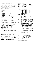
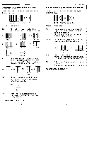
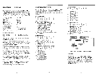
Jumper Block J6 (Channel Selection and SCSI ID) The following diagram shows the default settings of jumper block J6: Pin Pair SD I I I O I 0 0 0O J6 0 00 SD SD SD IC IC DC DC SP Description Use the three pin pairs marked SD to determine the SCSI ID of the host adapter. ID 7= VHF SD SD SD Default O O 1 ID 4 = O O SD SD SD O ID 6= O SD SD SD ID 3= O SD SD SD O ID 5= O SD SD SD O O ID 2= O O SD SD SD ID 1= () O O O O O ID 0= O O O SD SD SD SD SD SD IC Use the two pin pairs marked IC to select the host adapter REQ channel. You must also use pin pairs 10, I1, 12, and 19 on jumper block J9 to select an IRQ channel. IRQ 9 = O O IRQ 10= O O A IRQ 11= O O II2O 12 = IC IC IC IC IC IC Default IC IC DC The two pin pairs marked DC to select the host adapter DMA channel. Only DMA channel 0 is supported. O O DMA 0= O O DC DC Default SP Parity checking enabled or disabled. "No jumper = parity enabled; Jumper = parity disabled. 'denotes default configuration Jumper Block J7 (Floppy Drive Options) - AHA-1522 Only The following diagram shows the default settings of jumper block J7: Pin Pair FE DR, DA 0 0 0 0 J7 0 0 0 0 FE DR DR DA DA 16 10 DS Description Use this pin pair to determine whether the floppy controller on the host adapter is enabled or disabled. 'Jumper = floppy enabled (default); No jumper = floppy disabled. Use the four pin pairs marked DR and DA to set the floppy DMA request channel. 16, 10 CH 2= 0 0 0 O CH 3= O O DR DR DA DA Default DR DR DA DA Set Floppy IRQ Channel. 'Jumper 16 = Interrupt Channel 6 enabled; Jumper 10 = Interrupt Channel 10 enabled. DS Set to support floppy drive with dual speed spindle. "No jumper= disabled; Jumper = enabled. 'denotes default configuration.
-
 1
1 -
 2
2 -
 3
3 -
 4
4 -
 5
5 -
 6
6 -
 7
7 -
 8
8
 |
 |
