Adaptec AHA-1522B Installation Guide - Page 8
Floppy, Header, Internal, Aic-6260al
 |
UPC - 760884126073
View all Adaptec AHA-1522B manuals
Add to My Manuals
Save this manual to your list of manuals |
Page 8 highlights
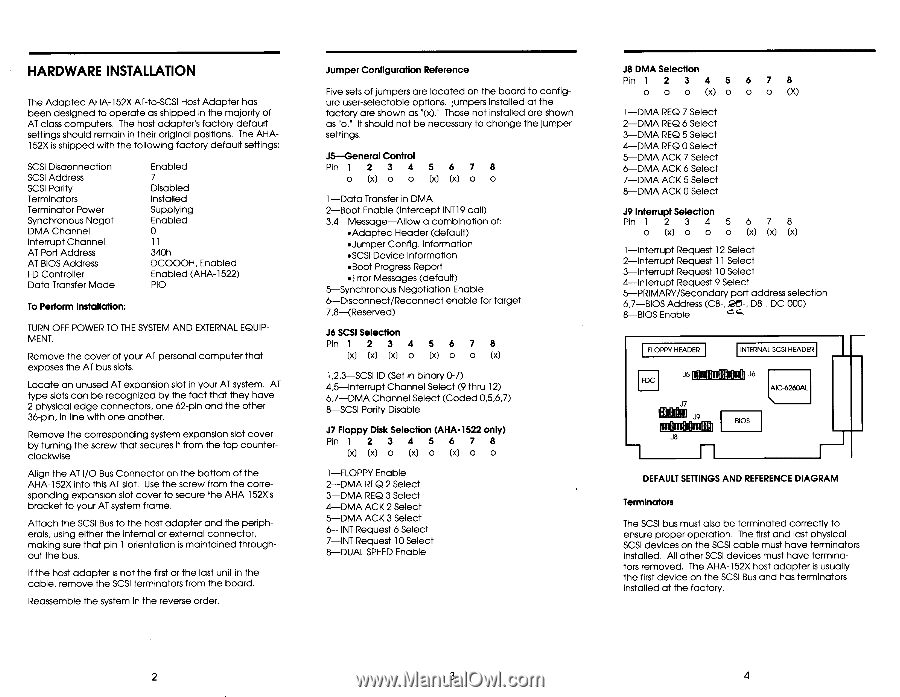
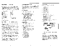
HARDWARE INSTALLATION The Adaptec AHA-152X AT-to-SCSI Host Adapter has been designed to operate as shipped in the majority of AT class computers. The host adapter's factory default settings should remain in their original positions. The AHA152X is shipped with the following factory default settings: SCSI Disconnection SCSI Address SCSI Parity Terminators Terminator Power Synchronous Negot. DMA Channel Interrupt Channel AT Port Address AT BIOS Address FD Controller Data Transfer Mode Enabled 7 Disabled Installed Supplying Enabled 0 11 340h DCOOOH, Enabled Enabled (AHA-1522) PIO To Perform Installation: TURN OFF POWER TO THE SYSTEM AND EXTERNAL EQUIPMENT. Remove the cover of your AT personal computer that exposes the AT bus slots. Locate an unused AT expansion slot in your AT system. AT type slots can be recognized by the fact that they have 2 physical edge connectors, one 62-pin and the other 36-pin, in line with one another. Remove the corresponding system expansion slot cover by turning the screw that secures it from the top counterclockwise. Align the AT I/O Bus Connector on the bottom of the AHA-152X into this AT slot. Use the screw from the corresponding expansion slot cover to secure the AHA-152X's bracket to your AT system frame. Attach the SCSI Bus to the host adapter and the peripherals, using either the internal or external connector, making sure that pin 1 orientation is maintained throughout the bus. If the host adapter is not the first or the last unit in the cable, remove the SCSI terminators from the board. Reassemble the system in the reverse order. Jumper Configuration Reference Five sets of jumpers are located on the board to configure user-selectable options. jumpers installed at the factory are shown as "(x)." Those not installed are shown as "o." It should not be necessary to change the jumper settings. J5-General Control Pin 1 2 3 4 5 6 7 8 o (x) O O (x) (x) 1-Data Transfer in DMA 2-Boot Enable (Intercept INT19 call) 3,4-Message-Allow a combination of: •Adaptec Header (default) •Jumper Config. Information •SCSI Device Information •Boot Progress Report •Error Messages (default) 5-Synchronous Negotiation Enable 6-Disconnect/Reconnect enable for target 7,8-(Reserved) J6 SCSI Selection Pin 1 2 3 4 5 6 7 8 (x) 00 o (x) o O (x) 1,2,3-SCSI ID (Set in binary 0-7) 4,5-Interrupt Channel Select (9 thru 12) 6,7-DMA Channel Select (Coded 0,5,6,7) 8-SCSI Parity Disable J7 Floppy Disk Selection (AHA-1522 only) Pin 1 2 3 4 5 6 7 8 (x) (x) o (x) O (x) O O 1-FLOPPY Enable 2-DMA REQ 2 Select 3-DMA REQ 3 Select 4-DMA ACK 2 Select 5-DMA ACK 3 Select 6-INT Request 6 Select 7-INT Request 10 Select 8-DUAL SPEED Enable J8 DMA Selection Pin 1 2 3 4 5 6 7 8 O O O (x) O O O (X) 1-DMA REQ 7 Select 2-DMA REQ 6 Select 3-DMA REQ 5 Select 4-DMA REQ 0 Select 5-DMA ACK 7 Select 6-DMA ACK 6 Select 7-DMA ACK 5 Select 8-DMA ACK 0 Select J9 Interrupt Selection Pin 1 2 3 4 5 o (x) O O O 67 8 (x) (x) (x) 1-Interrupt Request 12 Select 2-Interrupt Request 11 Select 3-Interrupt Request 10 Select 4-Interrupt Request 9 Select 5-PRIMARY/Secondary port address selection 6,7-BIOS Address (C8-,.Eff5-, D8-, DC-000) 8-BIOS Enable FLOPPY HEADER INTERNAL SCSI HEADER J5 FDC J7 MOM j ailWill I n J8 J6 AIC-6260AL BIOS DEFAULT SETTINGS AND REFERENCE DIAGRAM Terminators The SCSI bus must also be terminated correctly to ensure proper operation. The first and last physical SCSI devices on the SCSI cable must have terminators installed. All other SCSI devices must have terminators removed. The AHA-152X host adapter is usually the first device on the SCSI Bus and has terminators installed at the factory. 2 3 4
-
 1
1 -
2
-
 3
3 -
 4
4 -
 5
5 -
 6
6 -
 7
7 -
 8
8
 |
 |