Alpine INA-W910 Owner's Manual (english) - Page 129
Camera Input RCA Connector CAMERA IN, Video/Audio Output Connectors AUX OUTPUT
 |
View all Alpine INA-W910 manuals
Add to My Manuals
Save this manual to your list of manuals |
Page 129 highlights
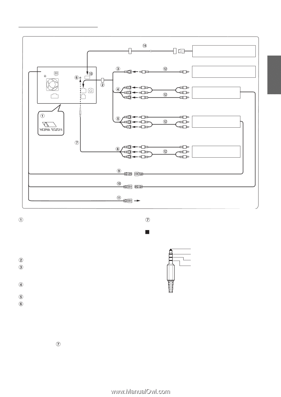
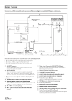
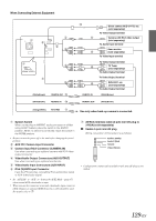
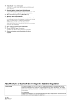
When Connecting External Equipment (White/Brown) (White/Brown) REMOTE OUT REMOTE IN (Orange/White) REVERSE REMOTE IN Direct camera HCE-C117D, etc. (sold separately) To Video Output terminal Camera with RCA video output (sold separately) To Audio Input terminal Rear monitor (sold separately) To Video Input terminal To Video Output terminal TV Tuner (sold separately) To Audio Output terminal To Video Output terminal DVE-5207, etc. (sold separately) To Audio Output terminal (White/Brown) REMOTE OUT (White/Brown) Use only when back-up camera is connected. System Switch When connecting an IMPRINT audio processor or divider using Ai-NET feature, place the switch in the EQ/DIV position. When no device is connected, leave the switch in the NORM position. • Be sure to turn the power off to the unit before changing the switch position. AUX I/O / Camera Input Connector Camera Input RCA Connector (CAMERA IN) Use when connecting an optional camera with RCA video output connector. Video/Audio Output Connectors (AUX OUTPUT) Use when connecting an optional monitor etc. Video/Audio Input Connectors (AUX INPUT) iPod (V)/AUX Input Connector Input the iPhone/video compatible iPod audio/video signal or AUX video/audio signal. • Set "AUX2 IN" to "AUX" in "Setting the AUX2 Mode" (page 67) when normal AUX video/audio is input. • When you use this connector as normal video/audio input connector (AUX 2 Input), an optional AV/RCA interface cable should be used. For details, refer to . AV/RCA interface cable (4-pole mini AV plug to 3-RCA) (sold separately) Usable 4-pole mini AV plug Wiring convention of this system is as follows: Audio L (White) Audio R (Red) Ground Video (Yellow) • Configuration commercially available 4-pole mini AV plugs is not unified. 129-EN
-
 1
1 -
2
-
3
-
4
-
5
-
6
-
7
-
8
-
9
-
10
-
11
-
12
-
13
-
14
-
15
-
16
-
17
-
18
-
19
-
20
-
21
-
22
-
23
-
24
-
25
-
26
-
27
-
28
-
29
-
30
-
31
-
32
-
33
-
34
-
35
-
36
-
37
-
38
-
39
-
40
-
41
-
42
-
43
-
44
-
45
-
46
-
47
-
48
-
49
-
50
-
51
-
52
-
53
-
54
-
55
-
56
-
57
-
58
-
59
-
60
-
61
-
62
-
63
-
64
-
65
-
66
-
67
-
68
-
69
-
70
-
71
-
72
-
73
-
74
-
75
-
76
-
77
-
78
-
79
-
80
-
81
-
82
-
83
-
84
-
85
-
86
-
87
-
88
-
89
-
90
-
91
-
92
-
93
-
94
-
95
-
96
-
97
-
98
-
99
-
100
-
101
-
102
-
103
-
104
-
105
-
106
-
107
-
108
-
109
-
110
-
111
-
112
-
113
-
114
-
115
-
116
-
117
-
118
-
119
-
120
-
121
-
122
-
123
-
 124
124 -
 125
125 -
 126
126 -
 127
127 -
 128
128 -
 129
129 -
 130
130 -
 131
131
 |
 |