Amana AEP222VAW Installation Instruction - Page 11
wire connection: Direct Wire, Bare Wire Torque Specifications
 |
UPC - 883049137407
View all Amana AEP222VAW manuals
Add to My Manuals
Save this manual to your list of manuals |
Page 11 highlights
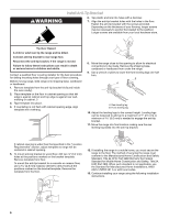
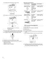
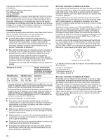
6. Use ³⁄₈" nut driver to connect the neutral (white) wire to the center terminal block post with one of the 10-32 hex nuts. as shown in the following Bare Wire Torque Specifications chart. A G A B F DE C A. 10-32 hex nut B. Line 1 (black) C. Bare (green) ground wire D. Ground-link screw E. Neutral (white) wire F. Line 2 (red) G. Terminal lug 7. Connect line 1 (black) and line 2 (red) wires to the outer terminal block posts with 10-32 hex nuts. 8. Securely tighten hex nuts. 9. Replace terminal block access cover. 3-wire connection: Direct Wire Use this method only if local codes permit connecting ground conductor to neutral supply wire. 1. Pull the conduit through the strain relief on cord/conduit plate on bottom of range. Allow enough slack to easily attach the wiring to the terminal block. A B B C D E A. Terminal lug B. Set screw C. Line 1 (black) wire D. Bare (green) ground wire E. Line 2 (red) wire Bare Wire Torque Specifications Attaching terminal lugs to the terminal block - 20 lbs-in. (2.3 N-m) Wire Awg Torque 8 gauge copper 6 gauge aluminum 25 lbs-in. (2.8 N-m) 35 lbs-in. (4.0 N-m) 3. Use ³⁄₈" nut driver to connect the bare (green) ground wire to the center terminal block post with one of the 10-32 hex nuts. F A E B C FE A. Terminal block B. Ground-link screw C. Cord/conduit plate D D. Line 2 (red) wire E. Bare (green) ground wire F. Line 1 (black) wire 2. Attach terminal lugs to line 1 (black), bare (green) ground, and line 2 (red) wires. Loosen (do not remove) the set screw on the front of the terminal lug and insert exposed wire end through bottom of terminal lugs. Securely tighten set screw to torque D C A. 10-32 hex nut B. Line 1 (black) C. Ground-link screw D. Bare (green) ground wire E. Line 2 (red) F. Terminal lug 4. Connect line 1 (black) and line 2 (red) wires to the outer terminal block posts with 10-32 hex nuts. 5. Securely tighten hex nuts. 6. Replace terminal block access cover. 11
-
 1
1 -
2
-
3
-
4
-
5
-
 6
6 -
 7
7 -
 8
8 -
 9
9 -
 10
10 -
 11
11 -
 12
12 -
 13
13 -
 14
14 -
 15
15 -
 16
16 -
17
-
18
-
19
-
20
-
21
-
22
-
23
-
24
 |
 |
