Amana AEP222VAW Installation Instruction - Page 5
Installation Instructions - door removal
 |
UPC - 883049137407
View all Amana AEP222VAW manuals
Add to My Manuals
Save this manual to your list of manuals |
Page 5 highlights
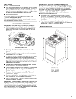
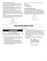
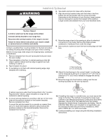
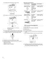
If connecting to a 4-wire system: This range is manufactured with the ground connected to the neutral by a link. The ground must be revised so the green ground wire of the 4-wire power supply cord is connected to the cabinet. See "Electrical Connection." Grounding through the neutral conductor is prohibited for new branch-circuit installations (1996 NEC); mobile homes; and recreational vehicles, or an area where local codes prohibit grounding through the neutral conductor. When a 4-wire receptacle of NEMA Type 14-50R is used, a matching UL listed, 4-wire, 250-volt, 40-amp, range power supply cord (pigtail) must be used. This cord contains 4 copper conductors with ring terminals or open-end spade terminals with upturned ends, terminating in a NEMA Type 14-50P plug on the supply end. The fourth (grounding) conductor must be identified by a green or green/yellow cover and the neutral conductor by a white cover. Cord should be Type SRD or SRDT with a UL listed strain relief and be at least 4 ft (1.22 m) long. The minimum conductor sized for the copper 4-wire power cord are: 40-amp circuit 2 No.-8 conductors 1 No.-10 white neutral 1 No.-8 green grounding If connecting to a 3-wire system: Local codes may permit the use of a UL listed, 3-wire, 250 volt, 40-amp range power supply cord (pigtail). This cord contains 3 copper conductors with ring terminals or open-end spade terminals with upturned ends, terminating in a NEMA Type 10-50P plug on the supply end. Connectors on the appliance end must be provided at the point the power supply cord enters the appliance. This uses a 3-wire receptacle of NEMA Type 10-50R. 3-wire receptacle (10-50R) 4-wire receptacle (14-50R) INSTALLATION INSTRUCTIONS Unpack Range WARNING Excessive Weight Hazard Use two or more people to move and install range. Failure to do so can result in back or other injury. 4. Pull cardboard bottom firmly to remove. 5. Use a wrench or pliers to loosen the leveling legs. Adjust the leveling legs to the correct height. Leveling legs can be loosened to add up to a maximum of 1" (2.5 cm). A maximum of 5.0 mm) is needed to engage the anti-tip bracket. NOTE: If height adjustment is made when range is standing, tilt the range back to adjust the front legs, then tilt forward to adjust the rear legs. 1. Do not use oven door handle to lift or move the range. 2. Remove shipping materials, tape and film from range. Keep cardboard bottom under range. Remove oven racks and parts package from inside oven. 6. Place cardboard or hardboard in front of range. Using 2 or more people, stand range back up onto cardboard or hardboard. 3. Take 4 cardboard corners from the carton. Stack one cardboard corner on top of another. Repeat with the other 2 corners. Place them lengthwise on the floor behind the A range to support the range when it is laid on its back. Using 2 or more people, firmly grasp the range and gently lay it on its back on the cardboard corners. A. Cardboard shipping base 5
-
 1
1 -
 2
2 -
 3
3 -
 4
4 -
 5
5 -
 6
6 -
 7
7 -
 8
8 -
 9
9 -
 10
10 -
 11
11 -
12
-
13
-
14
-
15
-
16
-
17
-
18
-
19
-
20
-
21
-
22
-
23
-
24
 |
 |
