Amana AGR3311WDW Installation Instruction - Page 9
Verify Anti-Tip Bracket Location, Level Range - parts manual
 |
UPC - 883049185231
View all Amana AGR3311WDW manuals
Add to My Manuals
Save this manual to your list of manuals |
Page 9 highlights
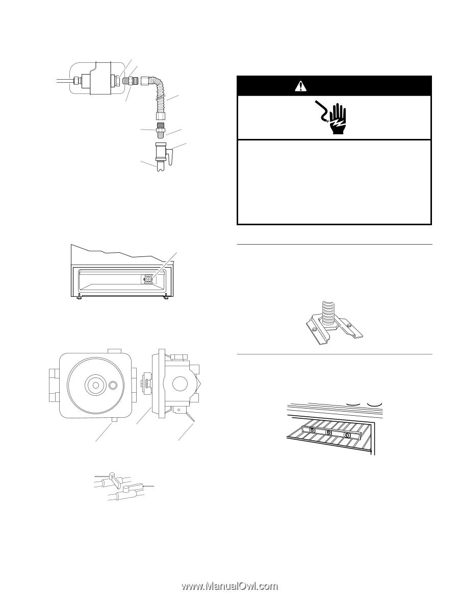
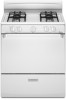
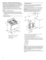
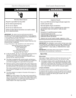
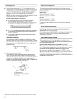
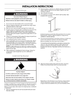
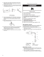
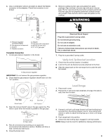
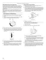
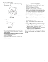
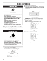
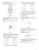
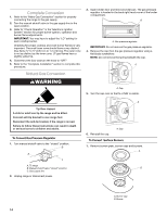
3. Use a combination wrench and pliers to attach the flexible connector to the adapters. Check that connector is not kinked. A B D C E F G H A. Pressure regulator connection fitting B. Use pipe-joint compound. C. Adapter D. Flexible connector E. Adapter F. Use pipe-joint compound. G. Manual shutoff valve H. ½" or ¾" gas pipe Complete Connection 1. Locate gas pressure regulator in the broiler. A A. Gas pressure regulator IMPORTANT: Do not remove the gas pressure regulator. 2. Check that the gas pressure regulator shutoff valve is in the "on" position. 6. Remove cooktop burner caps and grates from parts package. Align notches in burner caps with pins in burner base. Burner caps should be level when properly positioned. If burner caps are not properly positioned, surface burners will not light. Place burners, burner caps and grates on the cooktop. WARNING Electrical Shock Hazard Plug into a grounded 3 prong outlet. Do not remove ground prong. Do not use an adapter. Do not use an extension cord. Failure to follow these instructions can result in death, fire, or electrical shock. 7. Plug into a grounded 3 prong outlet. Verify Anti-Tip Bracket Location 1. Check that the anti-tip bracket is installed: ■ Look for the anti-tip bracket securely attached to the floor. ■ Slide the range back so the rear range foot is under the anti- tip bracket. Level Range 1. Place rack in oven. 2. Place level on rack and check levelness of range, first side to side; then front to back. Front View Front Side View Shutoff valve "ON" Position 3. Open the manual shutoff valve in the gas supply line. The valve is open when the handle is parallel to the gas pipe. A B A. Closed valve B. Open valve 4. Test all connections by brushing on an approved noncorrosive leak-detection solution. Bubbles will show a leak. Correct any leak found. 5. Close the broiler door. 3. If range is not level, pull range forward until rear leveling leg is removed from the anti-tip bracket. Use ³⁄₈" drive ratchet and wrench or pliers to adjust leveling legs up or down until range is level. 4. Push range back into position. 5. Check that rear leveling leg is engaged in anti-tip bracket. NOTE: Range must be level for satisfactory baking performance. 9
-
 1
1 -
2
-
3
-
 4
4 -
 5
5 -
 6
6 -
 7
7 -
 8
8 -
 9
9 -
 10
10 -
 11
11 -
 12
12 -
 13
13 -
 14
14 -
15
-
16
-
17
-
18
-
19
-
20
-
21
-
22
-
23
-
24
-
25
-
26
-
27
-
28
-
29
-
30
-
31
-
32
 |
 |