Ariens Max Zoom 48 Operation Manual - Page 10
Assembly, UNIT ASSEMBLY
 |
View all Ariens Max Zoom 48 manuals
Add to My Manuals
Save this manual to your list of manuals |
Page 10 highlights
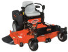
ASSEMBLY WARNING: AVOID INJURY. Read and understand entire Safety section before proceeding. UNIT ASSEMBLY Package Contents: Unit, Mower Deck and Literature Pack Preparation Checklist Refer to the Owner/Operator manual as required. 1. Unpack Unit - Remove shrink wrap and packaging materials. 2. Remove Unit From Container - Open Bypass Valves (dump valves) (See Moving the Unit with the Engine Off on page 16). Push unit from container onto a level surface. Close the bypass valves. 3. Tires - See Specifications on page 31. 4. Seat - See Seat Adjustments on page 13 and Service Position on page 18. 5. Position Steering Levers - Remove eccentric spacers and rotate steering levers to the operating position. Reinstall spacers. Tighten hardware securely. See Aligning the Steering Levers (Figure 14) on page 23. 1 21 3 CAUTION: Avoid injury! Explosive separation of tire and rim parts is possible when they are serviced incorrectly: • Do not attempt to mount a tire without the proper equipment and experience to perform the job. • Do not inflate the tires above the recommended pressure. • Do not weld or heat a wheel and tire assembly. Heat can cause an increase in air pressure resulting in an explosion. Welding can structurally weaken or deform the wheel. • Do not stand in front or over the tire assembly when inflating. Use a clip-on chuck and extension hose long enough to allow you to stand to one side. 1. Steering Levers 2. Seat 3. Mounting Hardware Figure 3 OF4110 6. Battery - Remove battery from unit and charge (See Battery on page 21). 7. Check Engine Crankcase - Check and add oil if needed. See Engine Manual for specifications. 8. Fill Engine Fuel Tank - Fill fuel tank. DO NOT OVERFILL! See Filling Fuel Tank on page 14. NOTE: See engine manual for fuel type. 9. Hardware - Check for loose hardware. GB - 10
-
 1
1 -
2
-
3
-
4
-
 5
5 -
 6
6 -
 7
7 -
 8
8 -
 9
9 -
 10
10 -
 11
11 -
 12
12 -
 13
13 -
 14
14 -
 15
15 -
16
-
17
-
18
-
19
-
20
-
21
-
22
-
23
-
24
-
25
-
26
-
27
-
28
-
29
-
30
-
31
-
32
-
33
-
34
-
35
-
36
 |
 |
