Ariens Power Brush 28 Owners Manual - Page 11
BRUSH ANGLE ADJUSTMENT, Fuel Shut-Off Valve, Recoil Starter Handle, Speed Selector
 |
View all Ariens Power Brush 28 manuals
Add to My Manuals
Save this manual to your list of manuals |
Page 11 highlights
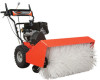
Fuel Shut-Off Valve IMPORTANT: The fuel shut-off valve MUST be in the closed position prior to transporting the unit. The fuel shut-off valve has two positions: Closed Position: Use this position to service, transport, or store the unit. Remote Trigger Locking Lock Pin Notches Open Position: Use this position to run the unit. Figure 5 OS7117 Recoil Starter Handle When pulled, handle will turn engine over. Speed Selector Position the Speed Selector in the appropriate speed notch to control forward and reverse travel. 6 5 4 321 Forward: (6) Fastest (1) Slowest 12 OS2401 Reverse: (1) Slow (2) Fast IMPORTANT: DO NOT change motion from forward to reverse with clutch engaged. Forward speed can be changed without declutching. BRUSH ANGLE ADJUSTMENT (Figure 6) To adjust the angle of the brush: 1. Squeeze the remote trigger on the right handlebar fully to disengage the lock pin. 2. Turn the unit left or right until the desired brush angle is achieved. 3. Release the remote trigger, ensuring that the lock pin is firmly seated in one of the locking notches. Figure 6 OS3040 BRUSH HEIGHT ADJUSTMENT (Figure 7) DANGER: Avoid injury from rotating parts. ALWAYS shut off engine before adjusting brush height. IMPORTANT: The brush may drive machine rearward if wheel drive is not engaged. Engage brush slowly with brush set at proper height. Adjust caster wheels to 1/8 - 1/4 inch (3 - 6 mm) above surface. For hard surfaces, adjust the caster wheels so that brush just touches surface. To adjust brush height: NOTE: Placing the spacers above the caster arm lowers brush height. Placing the spacers below the caster arm raises the brush height. To change brush height, remove the lock pin from the top of the caster fork. Support and raise the housing slightly, turn the spacers so the open end aligns with the flat cut sides on the caster fork, and then slide the spacers off of the fork. GB - 11
-
 1
1 -
2
-
3
-
4
-
5
-
 6
6 -
 7
7 -
 8
8 -
 9
9 -
 10
10 -
 11
11 -
 12
12 -
 13
13 -
 14
14 -
 15
15 -
 16
16 -
17
-
18
-
19
-
20
-
21
-
22
-
23
-
24
-
25
-
26
-
27
-
28
-
29
-
30
 |
 |
