Ariens Power Brush 28 Owners Manual - Page 25
FRICTION DISC REPLACEMENT, Remove Friction Disc
 |
View all Ariens Power Brush 28 manuals
Add to My Manuals
Save this manual to your list of manuals |
Page 25 highlights
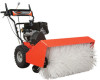
FRICTION DISC REPLACEMENT Remove Friction Disc 5 1 3 (Figure 28): 1. Shut off engine, disconnect spark plug 7 wire and allow unit to cool completely. NOTE: Brush assembly and frame must be separated in order to remove friction disc (See Figures 15 and 16). CAUTION: Always support Sno- Brush frame and brush assembly 2 when loosening the cap screws holding them together. CAUTION: Before tipping unit, remove enough fuel so that no spills occur. 2. Tip the tractor frame up onto its front on a level surface. 3. Remove both wheels. 4. Remove bottom cover by removing six hex bolts. 5. Disconnect pivot pin from the speed selector arm. Save the hardware for reinstallation. 6. Remove spring clip pin nearest drive sproket from hex shaft. 7. Remove left bearing flange from frame. 8. Slide hex shaft to the left to remove the pinion sprocket and friction disc assembly from the hex shaft. NOTE: Be sure to save washers between bearing and sliding fork for reassembly. 9. Remove friction disc assembly from frame. 10. Remove three screws holding friction disc to carrier bearing. 11. Remove old friction disc. Put the new friction disc in place, cup side to carrier bearing. 12. Reinstall three screws into new friction disc and carrier bearing. Torque to 5 - 6 lbf-ft. (6.8 - 8.13 N•m). 4 1. Hex Shaft 2. Bearing Flange 3. Speed Selector Arm 4. Friction Disc 6 5. Spring Clip 6. Drive Plate Assembly 7. Drive Sprocket Figure 28 OS7142 13. Insert new friction disc assembly into frame. Install washers onto carrier bearing and slide into speed selector arm. 14. Slide hex shaft through new friction plate assembly. Install pinion sprocket onto hex shaft and slide shaft into right bearing. 15. Install left bearing using hardware removed in step 7. 16. Reinstall clip pin into hex shaft. 17. Connect pivot pin to speed selector arm. See Speed Selector Adjustment on page 19. 18. Install bottom cover. 19. Reinstall wheels. 20. Return unit to upright position. 21. Connect spark plug wire to spark plug. 22. Adjust traction drive clutch. See Check Belt Finger Clearance (Figure 25) on page 24. GB - 25
-
 1
1 -
2
-
3
-
4
-
5
-
6
-
7
-
8
-
9
-
10
-
11
-
12
-
13
-
14
-
15
-
16
-
17
-
18
-
19
-
 20
20 -
 21
21 -
 22
22 -
 23
23 -
 24
24 -
 25
25 -
 26
26 -
 27
27 -
 28
28 -
 29
29 -
 30
30
 |
 |
