Ariens Power Brush 36 Owners Manual - Page 8
Assembly, Check Function of all Controls - belts
 |
View all Ariens Power Brush 36 manuals
Add to My Manuals
Save this manual to your list of manuals |
Page 8 highlights
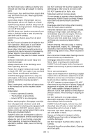
ASSEMBLY WARNING: AVOID INJURY. Read and understand the entire Safety section before proceeding. Unpacking Unit WARNING: Dropping or tipping over boxed unit could result in personal injury or damage to unit. Unfold Handlebar (Figure 3) 1. Remove the lower and loosen the upper hardware on the handlebar assembly. 2. Loosen the hardware on the shift rod. 3. Put the speed selector lever in the second reverse position. 4. Rotate the handlebars into operating position. IMPORTANT: Be careful not to damage cable spring hooks when rotating handlebars upward. 5. Install and tighten all hardware on the handlebar assembly and shift rod. 4 1 3 1 2 1. Mounting Hardware 2. Mounting Hardware 3. Shift Rod 4. Speed Selector Lever Figure 3 Check Tire Pressure Check tire pressure and adjust to the pressure listed on tire sidewall. CAUTION: Avoid injury! Explosive separation of tire and rim parts is possible when they are serviced incorrectly: • Do not attempt to mount a tire without the proper equipment and experience to perform the job. • Do not inflate the tires above the recommended pressure. • Do not weld or heat a wheel and tire assembly. Heat can cause an increase in air pressure resulting in an explosion. Welding can structurally weaken or deform the wheel. • Do not stand in front or over the tire assembly when inflating. Use a clip-on chuck and extension hose long enough to allow you to stand to one side. Check Engine Crankcase Oil IMPORTANT: Engine is shipped with 5W-30 oil in crankcase. Refer to Engine Manual for detailed instructions. Fill Engine Fuel Tank Refer to Engine Manual for proper fuel type and tank capacity. Refer to Filling Fuel Tank on page 13. Check Function of all Controls Ensure unit runs and performs properly. Refer to Operation on page 10. Run-in Attachment Belt 1. Start unit in a well-ventilated area according to Starting and Shut Off on page 13. 2. Engage attachment clutch lever and run attachment for about 15 minutes. 3. Stop unit, wait for all moving parts to stop, and remove spark plug wire. 4. Adjust belt finger, if necessary. See Check Belt Finger Clearance on page 21. 5. Adjust clutch idler according to Check Attachment Idler Arm Roller Clearance on page 20. GB - 8
-
 1
1 -
2
-
 3
3 -
 4
4 -
 5
5 -
 6
6 -
 7
7 -
 8
8 -
 9
9 -
 10
10 -
 11
11 -
 12
12 -
 13
13 -
14
-
15
-
16
-
17
-
18
-
19
-
20
-
21
-
22
-
23
-
24
-
25
-
26
-
27
-
28
-
29
-
30
-
31
-
32
 |
 |
