Asus A7V400-MX Motherboard DIY Troubleshooting Guide
Asus A7V400-MX Manual
 |
View all Asus A7V400-MX manuals
Add to My Manuals
Save this manual to your list of manuals |
Asus A7V400-MX manual content summary:
- Asus A7V400-MX | Motherboard DIY Troubleshooting Guide - Page 1
Motherboard A7V400-MX User Guide - Asus A7V400-MX | Motherboard DIY Troubleshooting Guide - Page 2
ASUSTeK COMPUTER INC. ("ASUS"). Product warranty or service will not be MANUAL OR PRODUCT. SPECIFICATIONS AND INFORMATION CONTAINED IN THIS MANUAL ARE FURNISHED FOR INFORMATIONAL USE ONLY, AND ARE SUBJECT TO CHANGE AT ANY TIME WITHOUT NOTICE, AND SHOULD NOT BE CONSTRUED AS A COMMITMENT BY ASUS. ASUS - Asus A7V400-MX | Motherboard DIY Troubleshooting Guide - Page 3
this guide vii A7V400-MX specifications summary viii Chapter 1: Product introduction 1.1 Welcome 1-2 1.2 Package contents 1-2 1.3 Special features 1-2 1.3.1 Product highlights 1-2 1.3.2 ASUS unique features 1-3 1.4 Before you proceed 1-4 1.5 Motherboard overview 1-5 1.5.1 Motherboard layout - Asus A7V400-MX | Motherboard DIY Troubleshooting Guide - Page 4
Creating a bootable floppy disk 2-2 Using the AwardBIOS Flash Utility 2-2 CrashFree BIOS feature 2-4 ASUS Update 2-4 2.2 BIOS beep codes 2-6 2.3 BIOS Setup program 2-6 2.3.1 BIOS menu bar 2-7 2.3.2 Legend bar 2-7 2.4 Main menu 2-9 2.5 Advanced menu 2-13 2.5.1 Chip Configuration 2-14 - Asus A7V400-MX | Motherboard DIY Troubleshooting Guide - Page 5
, uses and can radiate radio frequency energy and, if not installed and used in accordance with manufacturer's instructions, experienced radio/TV technician for help. The use of shielded cables for connection of the monitor to the graphics card is required to assure compliance with FCC regulations - Asus A7V400-MX | Motherboard DIY Troubleshooting Guide - Page 6
not try to fix it by yourself. Contact a qualified service technician or your retailer. Operation safety • Before installing the motherboard and adding devices on it, carefully read all the manuals that came with the package. • Before using the product, make sure all cables are correctly connected - Asus A7V400-MX | Motherboard DIY Troubleshooting Guide - Page 7
you perform certain tasks properly, take note of the following symbols used throughout this guide. WARNING. Information to prevent injury to yourself when trying to updates. 1. Websites The ASUS websites worldwide provide updated information on ASUS hardware and software products. Refer to the ASUS - Asus A7V400-MX | Motherboard DIY Troubleshooting Guide - Page 8
-MX specifications summary CPU Chipset Front Side Bus (FSB) Memory Expansion slots IDE Graphics Audio LAN USB Hardware monitoring Rear panel I/O ports Internal connectors Socket A for AMD Athlon™XP processors Thoroughbred/Barton core VIA KM400A VIA VT8235 CE 400/333/266/200 MHz 2 x 184-pin DDR - Asus A7V400-MX | Motherboard DIY Troubleshooting Guide - Page 9
intrusion Device drivers ASUS PC Probe ASUS Live Update Utility Award BIOS Flash Utility Adobe Acrobat Reader Trend Micro™ PC-cillin Anti-Virus Application User Guide ASUS A7V400-MX support CD UltraATA cable FDD cable I/O shield Micro-ATX form factor: 9.6 in x 9.6 in * Specifications are subject - Asus A7V400-MX | Motherboard DIY Troubleshooting Guide - Page 10
x - Asus A7V400-MX | Motherboard DIY Troubleshooting Guide - Page 11
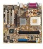
Chapter 1 This chapter describes the features of the motherboard. It includes brief descriptions of the motherboard components, and illustrations of the layout, jumper settings, and connectors. Product introduction - Asus A7V400-MX | Motherboard DIY Troubleshooting Guide - Page 12
for the following items. ASUS A7V400-MX motherboard.(Micro-ATX form factor: 9.6 in x 9.6 in) ASUS A7V400-MX support CD 40-pin 80-conductor ribbon cable for UltraATA133 IDE drives Ribbon cable for a 3.5-inch floppy drive Bag of extra jumper caps I/O shield User Guide Contact your retailer if any - Asus A7V400-MX | Motherboard DIY Troubleshooting Guide - Page 13
permanently damage the CPU. See page 2-23. ASUS CrashFree BIOS CrashFree BIOS allows users to restore BIOS data from a floppy disk even when BIOS code and data are corrupted. Users can now enjoy this feature without the need to buy a new ROM. See page 2-4. ASUS A7V400-MX motherboard user guide 1-3 - Asus A7V400-MX | Motherboard DIY Troubleshooting Guide - Page 14
install motherboard components or change any motherboard settings. • Unplug the power cord from the wall socket before touching any component. • Use a removing or plugging in any motherboard component. ® A7V400-MX A7V400-MX Onboard LED SB_PWR ON Standby Power OFF Powered Off 1-4 Chapter - Asus A7V400-MX | Motherboard DIY Troubleshooting Guide - Page 15
pin module) DDR DIMM2 (64 bit,184-pin module) PARALLEL PORT USBPWR34 USBPWR12 VGA USB1 USB2 USB2.0 M: USB3 B: USB4 Top: RJ-45 Top:Line In Middle:Line Out Bottom:Mic In VIA VT6103 SPDIF 6-channel Audio CODEC FP_AUDIO VIA KM400A Accelerated Graphics Port (AGP1) ® PCI1 A7V400-MX PCI2 CR2032 - Asus A7V400-MX | Motherboard DIY Troubleshooting Guide - Page 16
goes to the rear part of the chassis as indicated in the image below. It may be more convenient to install major cables, the CPU and modular components before fixing the motherboard inside the case frame. 1.5.3 Screw holes Place eight (8) screws into the holes indicated by circles to secure the - Asus A7V400-MX | Motherboard DIY Troubleshooting Guide - Page 17
of the socket base nearest to the lever hinge. LOCK LEVER CPU NOTCH Golden corner The CPU should drop easily into place. Do not force the CPU into the socket to avoid bending the pins. If the CPU does not fit, check its alignment and look for bent pins. ASUS A7V400-MX motherboard user guide 1-7 - Asus A7V400-MX | Motherboard DIY Troubleshooting Guide - Page 18
104 Pins 1.7 System memory 1.7.1 Overview The motherboard has two Double Data Rate (DDR) DIMM sockets that support up to 2GB unbuffered non-ECC PC2700/2100/1600 DDR SDRAM DIMMs. Each DIMM socket is double-sided. ® A7V400-MX A7V400-MX 184-Pin DDR DIMM Sockets 1.7.2 Memory configurations You may - Asus A7V400-MX | Motherboard DIY Troubleshooting Guide - Page 19
a DIMM. 1. Simultaneously press the retaining clips outward to unlock the DIMM. Support the DIMM lightly with your fingers when pressing the retaining clips. The DIMM might get damaged when it flips out with extra force. 2. Remove the DIMM from the socket. ASUS A7V400-MX motherboard user guide 1-9 - Asus A7V400-MX | Motherboard DIY Troubleshooting Guide - Page 20
2. Remove the system unit cover (if your motherboard is already installed in a chassis). 3. Remove the bracket opposite the slot that you intend to use. Keep the screw for later use. 4. Align the card connector with the slot and press firmly until the card is completely seated on the slot. 5. Secure - Asus A7V400-MX | Motherboard DIY Troubleshooting Guide - Page 21
Port (COM1) 5* Onboard Audio 6 Standard Floppy Disk Controller PCI devices. IRQ assignments for this motherboard PCI slot 1 PCI slot 2 PCI slot 3 AGP slot A B C D shared -- -- -- -- shared -- -- -- -- shared -- shared -- -- -- ASUS A7V400-MX motherboard user guide - Asus A7V400-MX | Motherboard DIY Troubleshooting Guide - Page 22
not support 3.3V AGP cards. ® A7V400-MX Keyed for 1.5v A7V400-MX Accelerated Graphics Port (AGP) 1.8.4 PCI slots Three 32-bit PCI slots are available on this motherboard. The slots support PCI cards such as LAN card, SCSI card, USB card, and other cards that comply with PCI specifications. This - Asus A7V400-MX | Motherboard DIY Troubleshooting Guide - Page 23
's internal frequency (the advertised CPU speed). The default CPU external frequency is 100MHz. If your CPU supports 200/166/ 133 MHz external frequency, adjust the DSW settings before installing the motherboard to the chassis. ® A7V400-MX DSW ON ON ON ON CPU AGP PCI 12345 12345 12345 200MHz - Asus A7V400-MX | Motherboard DIY Troubleshooting Guide - Page 24
using the connected USB devices. Set to +5VSB to wake up from S3 sleep mode (no power to CPU, DRAM in slow refresh, power supply in reduced power mode). Both jumpers are set to pins 1-2 (+5V) by default because not all computers have the appropriate power supply to support . A7V400-MX A7V400-MX USB - Asus A7V400-MX | Motherboard DIY Troubleshooting Guide - Page 25
, [2-3]. 4. Re-install the battery. 5. Plug the power cord and turn ON the computer. 6. Hold down the key during the boot process and enter BIOS setup to re-enter data. A7V400-MX A7V400-MX Clear RTC RAM CLRTC 12 23 Clear CMOS Normal (Default) ASUS A7V400-MX motherboard user guide 1-15 - Asus A7V400-MX | Motherboard DIY Troubleshooting Guide - Page 26
connectors on the motherboard. 1.10.1 Rear panel connectors 1 2 3 4 5 6 11 10 9 8 7 1. PS/2 mouse port. This green 6-pin connector port connects a tape player or other audio sources. In 6-channel mode, the function 2.0 devices. 9. VGA port. This port connects a VGA-compatible monitor. 10. - Asus A7V400-MX | Motherboard DIY Troubleshooting Guide - Page 27
other end to the floppy drive. (Pin 5 is removed to prevent incorrect insertion when using ribbon cables with pin 5 plug.) ® A7V400-MX FLOPPY NOTE: Orient the red markings on the floppy ribbon cable to PIN 1. PIN 1 A7V400-MX Floppy Disk Drive Connector ASUS A7V400-MX motherboard user guide 1-17 - Asus A7V400-MX | Motherboard DIY Troubleshooting Guide - Page 28
module that allows digital instead of analog sound input and output. SPDIF +5V SPDIFOUT GND ® A7V400-MX A7V400-MX Digital Audio Connector • When you input sound for S/PDIF IN, the LINE_OUT will output the sound. Mute LINE_OUT to impede sound output from S/PDIF IN. • The S/PDIF module is purchased - Asus A7V400-MX | Motherboard DIY Troubleshooting Guide - Page 29
A7V400-MX A7V400-MX USB 2.0 Header USB56 1 The USB/GAME module is purchased separately. 6. GAME/MIDI connector (16-1 pin GAME) This connector supports audio files. ® A7V400-MX A7V400-MX Game Connector GAME The USB/GAME module is purchased separately. ASUS A7V400-MX motherboard user guide - Asus A7V400-MX | Motherboard DIY Troubleshooting Guide - Page 30
fan connectors support cooling fans of 350mA ~ 740mA (8.88W max). Connect the fan cables to the fan connectors on the motherboard, making sure that the black wire of each cable matches the ground pin of the connector. CPU_FAN Rotation +12V GND ® A7V400-MX CHA_FAN GND +12V Rotation A7V400-MX 12 - Asus A7V400-MX | Motherboard DIY Troubleshooting Guide - Page 31
) This is an interface for front panel audio cable that allows convenient connection and control of audio devices. Line out_L NC Line out_R MICPWR MIC2 ® A7V400-MX FP_AUDIO A7V400-MX Front Panel Audio Connector ASUS A7V400-MX motherboard user guide BLINE_OUT_L BLINE_OUT_R +5VA AGND 1-21 - Asus A7V400-MX | Motherboard DIY Troubleshooting Guide - Page 32
A7V400-MX IDELED SMI Lead Reset SW ATX Power Switch* A7V400-MX System Panel Connectors * Requires an ATX power supply. • System Power LED Lead (3-1 pin PLED) This 3-1 pin connector This 2-pin connector allows you to manually place the system OFF, depending on the BIOS or OS settings. Pressing the - Asus A7V400-MX | Motherboard DIY Troubleshooting Guide - Page 33
Chapter 2 This chapter tells how to change system settings through the BIOS Setup Menus. Detailed descriptions of the BIOS parameters are also provided. BIOS information - Asus A7V400-MX | Motherboard DIY Troubleshooting Guide - Page 34
you to manage and update the motherboard Basic Input/Output System (BIOS) setup. 1. AwardBIOS Flash Utility (Updates the BIOS in DOS mode using a bootable floppy disk.) 2. ASUS CrashFree BIOS (Updates the BIOS using a floppy disk during POST.) 3. ASUS Update (Updates the BIOS in Windows® environment - Asus A7V400-MX | Motherboard DIY Troubleshooting Guide - Page 35
on the floppy disk. 5. After verification, AWDFLASH flashes the new BIOS file. Do not shut down the computer during the flash process. The computer returns to POST after the new BIOS file is copied. Updating the BIOS using a bootable floppy disk 1. Boot from the floppy disk. 2. At the "A:\" prompt - Asus A7V400-MX | Motherboard DIY Troubleshooting Guide - Page 36
BIOS Flash Utility." To use the CrashFree BIOS feature on this motherboard, install a VGA card into one of the expansion slots before rebooting the computer. On motherboards with onboard VGA, you will not see the screen display when the BIOS crashes even if you reboot the computer. 2.1.4 ASUS Update - Asus A7V400-MX | Motherboard DIY Troubleshooting Guide - Page 37
to complete the update process. If you selected the option to update the BIOS from a file, an Open window appears prompting you to locate the BIOS file. Select the file, click Open, then follow the screen instructions to complete the update process. ASUS A7V400-MX motherboard user guide 2-5 - Asus A7V400-MX | Motherboard DIY Troubleshooting Guide - Page 38
Video card not found or video card memory bad CPU overheated; System running at a lower frequency 2.3 BIOS Setup program This motherboard supports a programmable Low Pin Count (LPC) chip that you can update using the provided utility described in section "2.1 Managing and updating your BIOS." Use - Asus A7V400-MX | Motherboard DIY Troubleshooting Guide - Page 39
backward through the values for the highlighted field Page Up or + (plus) Scrolls forward through the values for the highlighted field Brings up a selection menu for the highlighted field Saves changes and exit ASUS A7V400-MX motherboard user guide 2-7 - Asus A7V400-MX | Motherboard DIY Troubleshooting Guide - Page 40
the Item Help window, the BIOS setup program also provides a General Help screen. You may launch this screen from any menu by simply pressing -menu appears. Use the legend keys to navigate and enter values within each sub-menu as you would within a menu. Use the key to return to the main menu - Asus A7V400-MX | Motherboard DIY Troubleshooting Guide - Page 41
and press . The password is now set to [Set]. This password allows full access to the BIOS Setup menus. To clear the password, highlight this field and press . When the same dialog box appear, press . The password is set to [Clear]. ASUS A7V400-MX motherboard user guide 2-9 - Asus A7V400-MX | Motherboard DIY Troubleshooting Guide - Page 42
need to erase the CMOS RAM, unplug the all the BIOS Setup. Select [System] to require the password before entering the system. Configuration options: [Setup] [System] Installed Memory [XXX MB] This field automatically displays the amount of conventional memory detected by the system during the boot - Asus A7V400-MX | Motherboard DIY Troubleshooting Guide - Page 43
Menu Item Specific manually. Before attempting to configure a hard disk drive, make sure you have the correct configuration information supplied by the drive manufacturer. Incorrect settings may cause the system to fail to recognize the installed hard disk. ASUS A7V400-MX motherboard user guide - Asus A7V400-MX | Motherboard DIY Troubleshooting Guide - Page 44
→← : Select Menu Enter : Select Sub-menu F10 : Save and Exit Manually enter the number of cylinders, heads and sectors per track for the drive. Refer to the drive documentation or the drive label for this information. After entering the IDE hard disk drive information into BIOS, use a disk utility - Asus A7V400-MX | Motherboard DIY Troubleshooting Guide - Page 45
[UDMA3] [UDMA4] [UDMA5] 2.5 Advanced menu CPU Type CPU Speed Cache RAM Current FSB Frequency Current DRAM Frequency DRAM Clock External Cache USB Legacy Support Init Display First AGP Display switch DDR voltage adjustment Chip Configuration I/O Device Configuration PCI Configuration AMD Athlon(tm - Asus A7V400-MX | Motherboard DIY Troubleshooting Guide - Page 46
allows you to adjust the DDR voltage. Configuration options: [2.6V] [2.5V] [Auto] 2.5.1 Chip Configuration Chip Configuration AGP & P2P Bridge Control DRAM Clock/Drive Control CPU & PCI Bus Control VIA OnChip IDE Device VGA Share Memory Size [32M] Select Menu Item Specific Help Press [Enter] to - Asus A7V400-MX | Motherboard DIY Troubleshooting Guide - Page 47
Menu Item Specific Help F1 : Help ↑↓ : Select Item -/+ : Change Value F5 : Setup Defaults ESC : Exit →← : Select Menu Enter : Select Sub-menu F10 : Save and Exit AGP Aperture Size [XXXMB] This field sets the size of mapped memory for AGP graphic [Manual ASUS A7V400-MX motherboard user guide 2-15 - Asus A7V400-MX | Motherboard DIY Troubleshooting Guide - Page 48
Menu Item Specific Help F1 : Help ↑↓ : Select Item -/+ : Change Value F5 : Setup Defaults ESC : Exit →← : Select Menu Enter : Select Sub-menu F10 and Active to CMD (Trcd) prameters. Configuration options: [Manual] [Auto By SPD] [Safe] DRAM CAS Latency : [4] [8] 2-16 Chapter 2: BIOS information - Asus A7V400-MX | Motherboard DIY Troubleshooting Guide - Page 49
frees the PCI bus when the CPU is accessing 8-bit ISA cards. This process consumes 50-60 PCI clocks without PCI delayed transaction. Set this field to [Disabled] when using ISA cards that are not PCI 2.2 compliant. Configuration options: [Disabled] [Enabled] ASUS A7V400-MX motherboard user guide - Asus A7V400-MX | Motherboard DIY Troubleshooting Guide - Page 50
[Enabled] [Enabled] [Auto] [Auto] [Auto] [Auto] [Auto] [Auto] [Auto] [Auto] Select Menu Item Specific Help Press [Enter] to enable or disable IDE DMA transfer access. F1 : Help ↑↓ : Select Item -/+ automatic configuration. Configuration options: [Disabled] [Auto] 2-18 Chapter 2: BIOS information - Asus A7V400-MX | Motherboard DIY Troubleshooting Guide - Page 51
Use DMA EPP Mode Select AC97 Audio Onboard LAN Onboard LAN Boot ROM Game Port Address MIDI Port Address MIDI Port IRQ [3F8/IRQ4] [2F8/IRQ3] [378/IRQ7] [ECP+EPP] [3] [EPP1.7] [Auto] [Enabled] [Disabled] [201] [Disabled] 10 Select Menu Item Specific .7] ASUS A7V400-MX motherboard user guide 2-19 - Asus A7V400-MX | Motherboard DIY Troubleshooting Guide - Page 52
] PCI/VGA Palette Snoop Assign IRQ for VGA Assign IRQ for USB [Disabled] [Enabled] [Enabled] Select Menu Item Specific Help BIOS can automatically configure all the boot Plug and Play compatible devices. If you choose [Auto], you cannot select IRQ DMA and memory base address fields, since BIOS - Asus A7V400-MX | Motherboard DIY Troubleshooting Guide - Page 53
sub-menu is activated when the Resources Controlled by parameter is set to [Manual]. Select [PCI Device] to assign an IRQ address to a Plug and Play device. Setting to [Reserved] reserves the IRQ address. Configuration options: [PCI Device] [Reserved] ASUS A7V400-MX motherboard user guide 2-21 - Asus A7V400-MX | Motherboard DIY Troubleshooting Guide - Page 54
Video Off Method C.O.P. Control PWR Button < 4 Sec Power Up Control Hardware Monitor [S1&S3] [User Define] [Disabled] [Disabled] [Suspend -> Off] [Auto] [V/H SYNC+Blank] [85 degree] [Instant-off] Select Menu Item Specific Help Select the ACPI state used [On] [Off] 2-22 Chapter 2: BIOS information - Asus A7V400-MX | Motherboard DIY Troubleshooting Guide - Page 55
On PCI Devices [Disabled] When set to [Enabled], this parameter allows tyou to turn on the system through a PCI LAN or modem card. This feature requires an ATX power supply that provides at least 1A on the +5VSB lead. Configuration options: [Disabled] [Enabled] ASUS A7V400-MX motherboard user guide - Asus A7V400-MX | Motherboard DIY Troubleshooting Guide - Page 56
use specific keys When set to [Enabled], this parameter allows you to use the PS/2 keyboard to turn on the system. Configuration When set to [Enabled], this parameter allows you to use the PS/2 mouse to turn on the system. This manual setup. Configuration options: [Disabled] [Enabled] 2-24 Chapter - Asus A7V400-MX | Motherboard DIY Troubleshooting Guide - Page 57
RPM). If any of the fans is not connected to the motherboard, that field shows 0RPM. Vcore [XX.XX V] +3.3V [XX.XX V] +5V [XX.XX V] +12V [XX.XX V] The onboard hardware monitor automatically detects the voltage output through the onboard voltage regulators. ASUS A7V400-MX motherboard user guide 2-25 - Asus A7V400-MX | Motherboard DIY Troubleshooting Guide - Page 58
] [On] [Enabled] Select Menu Item Specific Help Select your boot device priority. F1 : Help ↑↓ : Select Item -/+ : Change Value F5 : Setup Defaults ESC : Exit →← : Select Menu Enter : Select Sub-menu F10 : Save and Exit First/Second/Third/Fourth Boot Device The Boot Menu allows you to select 13 - Asus A7V400-MX | Motherboard DIY Troubleshooting Guide - Page 59
APIC Mode [Enabled] When enabled, this option allows you to distribute interrupt routings other than the 16 IRQs. The Programmable Interrupt Controller (PIC) setting allows you to use the 16 IRQs only. Configuration options: [Disabled] [Enabled] ASUS A7V400-MX motherboard user guide 2-27 - Asus A7V400-MX | Motherboard DIY Troubleshooting Guide - Page 60
Optimized Defaults Discard Changes Save Changes Select Menu Item Specific Help This option saves data to CMOS and exits the BIOS setup. F1 : Help ↑↓ : Select Item -/+ : Change Value F5 : Setup Defaults ESC : Exit →← : Select Menu Enter : Select Sub-menu F10 : Save and Exit Save & Exit Setup - Asus A7V400-MX | Motherboard DIY Troubleshooting Guide - Page 61
Chapter 3 This chapter describes the contents of the support CD that comes with the motherboard package. Software support - Asus A7V400-MX | Motherboard DIY Troubleshooting Guide - Page 62
an operating system This motherboard supports Windows® 98SE/Me/2000/XP operating systems (OS). Always install the latest OS version and corresponding updates so you can maximize the features of your hardware. Because motherboard settings and hardware options vary, use the setup procedures presented - Asus A7V400-MX | Motherboard DIY Troubleshooting Guide - Page 63
utility continuously monitors your computer systems vital components such as fan rotations, CPU temperature, and system voltages, and alerts you on any detected problems. This utility helps you keep your computer at a healthy operating condition. ASUS A7V400-MX motherboard user guide 3-3 - Asus A7V400-MX | Motherboard DIY Troubleshooting Guide - Page 64
Install ASUS Update The ASUS Update is a utility that allows you to update the motherboard BIOS and drivers. This utility requires an Internet connection either through a network or an Internet Service Provider (ISP). PC-CILLIN This item installs the PC-cillin anti-virus program. View the PC-cillin
-
 1
1 -
 2
2 -
 3
3 -
 4
4 -
 5
5 -
 6
6 -
 7
7 -
8
-
9
-
10
-
11
-
12
-
13
-
14
-
15
-
16
-
17
-
18
-
19
-
20
-
21
-
22
-
23
-
24
-
25
-
26
-
27
-
28
-
29
-
30
-
31
-
32
-
33
-
34
-
35
-
36
-
37
-
38
-
39
-
40
-
41
-
42
-
43
-
44
-
45
-
46
-
47
-
48
-
49
-
50
-
51
-
52
-
53
-
54
-
55
-
56
-
57
-
58
-
59
-
60
-
61
-
62
-
63
-
64
 |
 |

Motherboard
A7V400-MX
User Guide