Asus A7V400-MX Motherboard DIY Troubleshooting Guide - Page 15
Motherboard overview - audio connector
 |
View all Asus A7V400-MX manuals
Add to My Manuals
Save this manual to your list of manuals |
Page 15 highlights
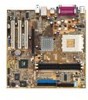
ATX Power Connector PRI_IDE SEC_IDE 24.5cm (9.6in) 1.5 Motherboard overview 1.5.1 Motherboard layout 24.5cm (9.6in) PS/2KBMS T: Mouse B: Keyboard COM1 Socket 462 CPU_FAN DSW FLOPPY DDR DIMM1 (64 bit,184-pin module) DDR DIMM2 (64 bit,184-pin module) PARALLEL PORT USBPWR34 USBPWR12 VGA USB1 USB2 USB2.0 M: USB3 B: USB4 Top: RJ-45 Top:Line In Middle:Line Out Bottom:Mic In VIA VT6103 SPDIF 6-channel Audio CODEC FP_AUDIO VIA KM400A Accelerated Graphics Port (AGP1) ® PCI1 A7V400-MX PCI2 CR2032 3V Lithium Cell CMOS Power VIA VT8235CE PCI3 USBPWR56 CLRTC SB_PWR AUX1 CD1 USB56 COM2 Super I/O CHA_FAN1 CHASSIS GAME PANEL 2Mbit Low Pin Count USBPWR12 USBPWR34 2 1 +5V 3 2 +5VSB (Default) USBPWR56 12 23 +5V (Default) +5VSB CLRTC 12 23 Clear CMOS Normal (Default) ASUS A7V400-MX motherboard user guide 1-5
-
 1
1 -
2
-
3
-
4
-
5
-
6
-
7
-
8
-
9
-
 10
10 -
 11
11 -
 12
12 -
 13
13 -
 14
14 -
 15
15 -
 16
16 -
 17
17 -
 18
18 -
 19
19 -
 20
20 -
21
-
22
-
23
-
24
-
25
-
26
-
27
-
28
-
29
-
30
-
31
-
32
-
33
-
34
-
35
-
36
-
37
-
38
-
39
-
40
-
41
-
42
-
43
-
44
-
45
-
46
-
47
-
48
-
49
-
50
-
51
-
52
-
53
-
54
-
55
-
56
-
57
-
58
-
59
-
60
-
61
-
62
-
63
-
64
 |
 |
