Asus A88XM-A/USB 3.1 A88XM-A/USB 3.1 Users manual English - Page 10
Layout contents, ATX power connectors 24-pin EATXPWR, 4-pin ATX12V - cpu support
 |
View all Asus A88XM-A/USB 3.1 manuals
Add to My Manuals
Save this manual to your list of manuals |
Page 10 highlights
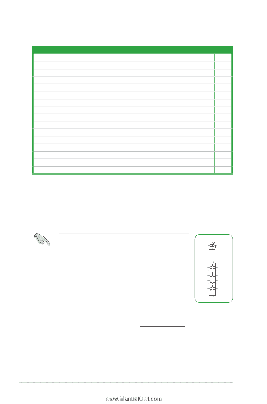
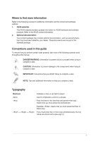
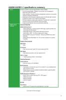
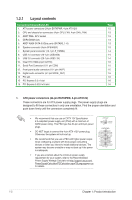
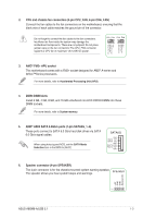
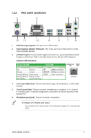
1.2.1 Layout contents Connectors/Jumpers/Slots/LED 1. ATX power connectors (24-pin EATXPWR, 4-pin ATX12V) 2. CPU and chassis fan connectors (4-pin CPU_FAN, 4-pin CHA_FAN) 3. AMD® FM2+ APU socket 4. DDR3 DIMM slots 5. AMD® A88X SATA 6.0Gb/s ports (SATA6G_1~6) 6. Speaker connector (4-pin SPEAKER) 7. System panel connector (10-1 pin F_PANEL) 8. USB 2.0 connector (10-1 pin USB3456) 9. USB 3.0 connector (20-1 pin USB3_34) 10. Clear RTC RAM (2-pin CLRTC) 11. Serial Port Connector (10-1 pin COM) 12. Front panel audio connector (10-1 pin AAFP) 13. Digital audio connector (4-1 pin SPDIF_OUT) 14 PCI slot 15 PCI Express 2.0 x1 slot 16 PCI Express 3.0/2.0 x16 slot Page 1-2 1-3 1-3 1-3 1-3 1-3 1-4 1-4 1-4 1-5 1-5 1-5 1-5 1-6 1-6 1-6 1. ATX power connectors (24-pin EATXPWR, 4-pin ATX12V) These connectors are for ATX power supply plugs. The power supply plugs are designed to fit these connectors in only one orientation. Find the proper orientation and push down firmly until the connectors completely fit. • We recommend that you use an EATX 12V Specification 2.0‑compliant power supply unit (PSU) with a minimum of 300W power rating. This PSU type has 24-pin and 8-pin power plugs. ATX12V GND GND PIN 1 +12V DC +12V DC EATXPWR • DO NOT forget to connect the 4-pin ATX +12V power plug. +3 Volts +12 Volts GND +5 Volts Otherwise, the system will not boot up. +12 Volts +5V Standby +5 Volts +5 Volts Power OK -5 Volts GND GND • We recommend that you use a PSU with higher power output +5 Volts GND GND GND when configuring a system with more power-consuming +5 Volts GND PSON# GND devices or when you intend to install additional devices. The +3 Volts +3 Volts -12 Volts +3 Volts system may become unstable or may not boot up if the power PIN 1 is inadequate. • If you are uncertain about the minimum power supply requirement for your system, refer to the Recommended Power Supply Wattage Calculator at http://support.asus.com/ PowerSupplyCalculator/PSCalculator.aspx?SLanguage=en-us for details. 1-2 Chapter 1: Product introduction
-
 1
1 -
2
-
3
-
4
-
 5
5 -
 6
6 -
 7
7 -
 8
8 -
 9
9 -
 10
10 -
 11
11 -
 12
12 -
 13
13 -
 14
14 -
 15
15 -
16
-
17
-
18
-
19
-
20
-
21
-
22
-
23
-
24
-
25
-
26
-
27
-
28
-
29
-
30
-
31
-
32
-
33
-
34
-
35
-
36
 |
 |