Asus A8V A8V-VM User's Manual for English Edition - Page 24
System memory - windows 7
 |
View all Asus A8V manuals
Add to My Manuals
Save this manual to your list of manuals |
Page 24 highlights
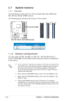
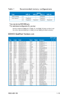
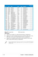
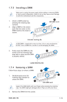
1.7 System memory 1.7.1 Overview The motherboard comes with four 184-pin Double Data Rate (DDR) Dual Inline Memory Module (DIMM) sockets. The following figure illustrates the location of the sockets: DIMM_A1 DIMM_A2 DIMM_B1 DIMM_B2 A8V-VM R A8V-VM 184-pin DDR DIMM Sockets Dual-channel mode Pair 1 Pair 2 Sockets DIMM_A1 and DIMM_B1 DIMM_A2 and DIMM_B2 1.7.2 Memory configurations You may install 128 MB, 256 MB, 512 MB, and 1 GB unbuffered ECC or non-ECC DDR DIMMs into the DIMM sockets using the memory configuration in this section. • If you install four 1 GB memory modules, the system may detect less than 3 GB of the total memory because of address space allocation for other critical functions. This limitation applies to Windows XP 32-bit version operating system since it does not support Physical Address Extension(PAE). • When using one DDR DIMM module, insert it into slot DIMM_B1 only. • When using two DDR DIMM modules, insert them into DIMM_A1 and DIMM_B1 slots. • Always install DIMMs with the same CAS latency. For optimum compatibility, we recommend that you obtain memory modules from the same vendor. Refer to the DDR400 Qualified Vendors List on the next page for details. 1-12 Chapter 1: Product introduction
-
 1
1 -
2
-
3
-
4
-
5
-
6
-
7
-
8
-
9
-
10
-
11
-
12
-
13
-
14
-
15
-
16
-
17
-
18
-
 19
19 -
 20
20 -
 21
21 -
 22
22 -
 23
23 -
 24
24 -
 25
25 -
 26
26 -
 27
27 -
 28
28 -
 29
29 -
30
-
31
-
32
-
33
-
34
-
35
-
36
-
37
-
38
-
39
-
40
-
41
-
42
-
43
-
44
-
45
-
46
-
47
-
48
-
49
-
50
-
51
-
52
-
53
-
54
-
55
-
56
-
57
-
58
-
59
-
60
-
61
-
62
-
63
-
64
-
65
-
66
-
67
-
68
-
69
-
70
-
71
-
72
-
73
-
74
-
75
-
76
-
77
-
78
-
79
-
80
-
81
-
82
 |
 |
