Asus AP120-E1 User Guide - Page 32
hooks inward.
 |
View all Asus AP120-E1 manuals
Add to My Manuals
Save this manual to your list of manuals |
Page 32 highlights
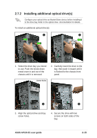
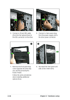
5 6 5. Connect a 40-pin IDE cable (from the first optical drive) to the IDE connector on the drive. 6. Connect a 4-pin power plug from the power supply unit to the drive power connector. 7 8 7. Remove the front panel bay cover opposite the drive bay you used by pressing the hooks inward. Follow the same procedures when installing additional optical drives. 8. Re-install the front panel and side covers when done. 2-16 Chapter 2: Hardware setup
-
 1
1 -
2
-
3
-
4
-
5
-
6
-
7
-
8
-
9
-
10
-
11
-
12
-
13
-
14
-
15
-
16
-
17
-
18
-
19
-
20
-
21
-
22
-
23
-
24
-
25
-
26
-
 27
27 -
 28
28 -
 29
29 -
 30
30 -
 31
31 -
 32
32 -
 33
33 -
 34
34 -
 35
35 -
 36
36 -
 37
37 -
38
-
39
-
40
-
41
-
42
-
43
-
44
-
45
-
46
-
47
-
48
-
49
-
50
-
51
-
52
 |
 |

Chapter 2:
Hardware setup
2-16
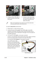
5.
Connect a 40-pin IDE cable
(from the first optical drive) to
the IDE connector on the drive.
6.
Connect a 4-pin power plug
from the power supply unit to
the drive power connector.
6
5
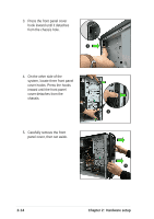
7.
Remove the front panel bay
cover opposite the drive bay
you used by pressing the
hooks inward.
Follow the same procedures
when installing additional
optical drives.
8
7
8.
Re-install the front panel and
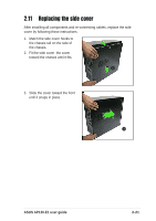
side covers when done.