Asus AP120-E1 User Guide - Page 41
the retention module hole
 |
View all Asus AP120-E1 manuals
Add to My Manuals
Save this manual to your list of manuals |
Page 41 highlights
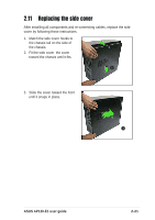
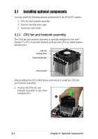
• The retention module base is already installed on the motherboard upon purchase. • Do not remove the retention module base when installing the CPU or installing other system components. 2. Align the retention bracket with the rails on the side of the CPU 2 fan. 3. Attach the retention bracket hook into the retention module hole. 4. Carefully press down the locking lever on the other side of the retention bracket. 5. Attach the locking lever hook into the retention module hole to secure the fan and heatsink assembly in place. 6. Follow steps 2 to 5 to re-install the second retention bracket. 3 4 5 The illustrations are for reference only and may not exactly match the actual component. ASUS AP120-E1 user guide 3-3
-
 1
1 -
2
-
3
-
4
-
5
-
6
-
7
-
8
-
9
-
10
-
11
-
12
-
13
-
14
-
15
-
16
-
17
-
18
-
19
-
20
-
21
-
22
-
23
-
24
-
25
-
26
-
27
-
28
-
29
-
30
-
31
-
32
-
33
-
34
-
35
-
 36
36 -
 37
37 -
 38
38 -
 39
39 -
 40
40 -
 41
41 -
 42
42 -
 43
43 -
 44
44 -
 45
45 -
 46
46 -
47
-
48
-
49
-
50
-
51
-
52
 |
 |

3-3
ASUS AP120-E1 user guide
2
3
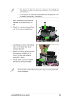
2.
Align the retention bracket with
the rails on the side of the CPU
fan.
3.
Attach the retention bracket hook
into the retention module hole.
•
The retention module base is already installed on the motherboard
upon purchase.
•
Do not remove the retention module base when installing the CPU
or installing other system components.
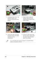
4.
Carefully press down the locking
lever on the other side of the
retention bracket.
5.
Attach the locking lever hook into
the retention module hole to
secure the fan and heatsink
assembly in place.
6.
Follow steps 2 to 5 to re-install
the second retention bracket.
4
5
The illustrations are for reference only and may not exactly match the
actual component.