Asus AT4NM10T-I User Manual - Page 12
Asus AT4NM10T-I Manual
 |
View all Asus AT4NM10T-I manuals
Add to My Manuals
Save this manual to your list of manuals |
Page 12 highlights
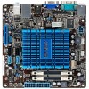
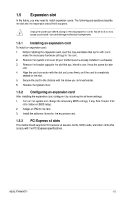
1.2 1.2.1 Motherboard overview Motherboard layout Ensure that you install the motherboard into the chassis in the correct orientation. The edge with external ports goes to the rear part of the chassis. 1 2 3 17.0cm(6.7in) 4 5 6 7 KB_USB56 CHA_FAN ATX12V LVDS COM CPU_FAN DDR3 SO-DIMM_A1 (64bit, 204-pin module) Intel® Atom™ processor D425 VGA COM2 PS2_USBPW1-6 EATXPWR Place this side towards the rear of the chassis. LPT DDR3 SO-DIMM_A2 (64bit, 204-pin module) Super I/O USB34 AT4NM10T-I 17.0cm(6.7in) LAN1_USB12 RTL 8111E Intel® NM10 SB_PWR 2 8 9 8Mb BIOS AUDIO AAFP VIA VT1705 Lithium Cell CMOS Power JMB 362 SATA3G_E2 SATA3G_2 CHASSIS CLRTC SPEAKER USB78 USBPW78 SATA3G_E1 SATA3G_1 F_PANEL SPDIF_OUT PCIEX4_1 17 15 16 15 14 13 12 11 10 Place four screws into the holes indicated by circles to secure the motherboard to the chassis. DO NOT overtighten the screws! Doing so can damage the motherboard. 1.2.2 1. 2. 3. 4. 5. 6. 7. 8. 9. Layout contents Page 1-16 1-10 1-15 1-13 1-14 1-3 1-3 1-12 1-12 10. 11. 12. 13. 14. 15. 16. 17. Connectors/Jumpers/Slots/LED System panel connector (10-1 pin F_PANEL) Clear RTC RAM (3-pin CLRTC) Onboard LED Serial ATA connectors (7-pin SATA3G_1, SATA3G_2, SATA3G_E1, SATA3G_E2) USB connectors (10-1 pin USB78) Keyboard/mouse power and USB device wake-up (3-pin PS2_USBPW1-6, 3-pin USBPW7-8) Page 1-12 1-7 1-1 1-11 1-11 Connectors/Jumpers/Slots/LED LPT connector (26-1 pin LPT ) ATX power connectors (24-pin EATXPWR, 4-pin ATX12V) Serial port connector (10-1 pin COM2) CPU and chassis fan connectors (4-pin CPU_FAN, 4-pin CHA_FAN) LVDS connector (30-pin LVDS) Intel® Atom™ D425 processor DDR3 DIMM sockets Chassis intrusion connector (4-1 pin CHASSIS) Internal speaker connector (4-pin SPEAKER) Digital audio connector (4-1 pin SPDIF_OUT) 1-15 1-8 Front panel audio connector (10-1 pin AAFP) 1-13 ASUS AT4NM10T-I 1-2
-
 1
1 -
2
-
3
-
4
-
5
-
6
-
 7
7 -
 8
8 -
 9
9 -
 10
10 -
 11
11 -
 12
12 -
 13
13 -
 14
14 -
 15
15 -
 16
16 -
 17
17 -
18
-
19
-
20
-
21
-
22
-
23
-
24
-
25
-
26
-
27
-
28
-
29
-
30
-
31
-
32
-
33
-
34
-
35
-
36
-
37
-
38
-
39
-
40
-
41
-
42
-
43
-
44
 |
 |
