Asus AT4NM10T-I User Manual - Page 20
Asus AT4NM10T-I Manual
 |
View all Asus AT4NM10T-I manuals
Add to My Manuals
Save this manual to your list of manuals |
Page 20 highlights
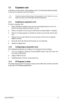
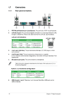
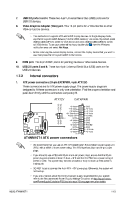
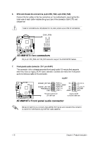
7. 8. USB 2.0 ports 3 and 4. These two 4-pin Universal Serial Bus (USB) ports are for USB 2.0 devices. Video Graphics Adapter (VGA) port. This 15-pin port is for a VGA monitor or other VGA-compatible devices. • This motherboard supports VGA and LVDS display devices. In Single Display mode, use the hot keys to switch between VGA to LVDS device or vice versa. By default, press ++ to switch to VGA device and press ++ to switch to LVDS device. To set your preferred hot keys, double-click from the Windows notification area and select Hot Keys. • Before removing the current display device, connect the display device that you want to use, then press the hot keys to switch to that device. 9. COM port. This 9-pin COM1 port is for pointing devices or other serial devices. 10. USB 2.0 ports 5 and 6. These two 4-pin Universal Serial Bus (USB) ports are for USB 2.0 devices. 1.7.2 1. Internal connectors ATX power connectors (24-pin EATXPWR, 4-pin ATX12V) These connectors are for ATX power supply plugs. The power supply plugs are designed to fit these connectors in only one orientation. Find the proper orientation and push down firmly until the connectors completely fit. ATX12V +12V DC +12V DC EATXPWR GND +5 Volts +5 Volts +5 Volts -5 Volts GND GND GND PSON# GND -12 Volts +3 Volts +3 Volts +12 Volts +12 Volts +5V Standby Power OK PIN 1 GND +5 Volts GND +5 Volts GND +3 Volts +3 Volts PIN 1 AT4NM10T-I ATX power connectors • We recommend that you use an ATX 12V Specification 2.0‑compliant power supply unit (PSU) with a 450W or lower power rating. This PSU type has 24-pin and 4-pin power plugs. • If you intend to use a PSU with 20-pin and 4-pin power plugs, ensure that the 20-pin power plug can provide at least 15 A on +12 V and that the PSU has a power rating of 450W or lower. The system may become unstable or may not boot up if the power is inadequate. • DO NOT forget to connect the 4-pin ATX +12V power plug. Otherwise, the system will not boot up. • If you are uncertain about the minimum power supply requirement for your system, refer to the Recommended Power Supply Wattage Calculator at http://support.asus. com/PowerSupplyCalculator/PSCalculator.aspx?SLanguage=en-us for details. ASUS AT4NM10T-I AT4NM10T-I GND GND 1-10
-
 1
1 -
2
-
3
-
4
-
5
-
6
-
7
-
8
-
9
-
10
-
11
-
12
-
13
-
14
-
 15
15 -
 16
16 -
 17
17 -
 18
18 -
 19
19 -
 20
20 -
 21
21 -
 22
22 -
 23
23 -
 24
24 -
 25
25 -
26
-
27
-
28
-
29
-
30
-
31
-
32
-
33
-
34
-
35
-
36
-
37
-
38
-
39
-
40
-
41
-
42
-
43
-
44
 |
 |