Asus B75M-PLUS B75M-PLUS User's Manual - Page 11
Central Processing Unit (CPU), Layout contents - lga1155
 |
View all Asus B75M-PLUS manuals
Add to My Manuals
Save this manual to your list of manuals |
Page 11 highlights
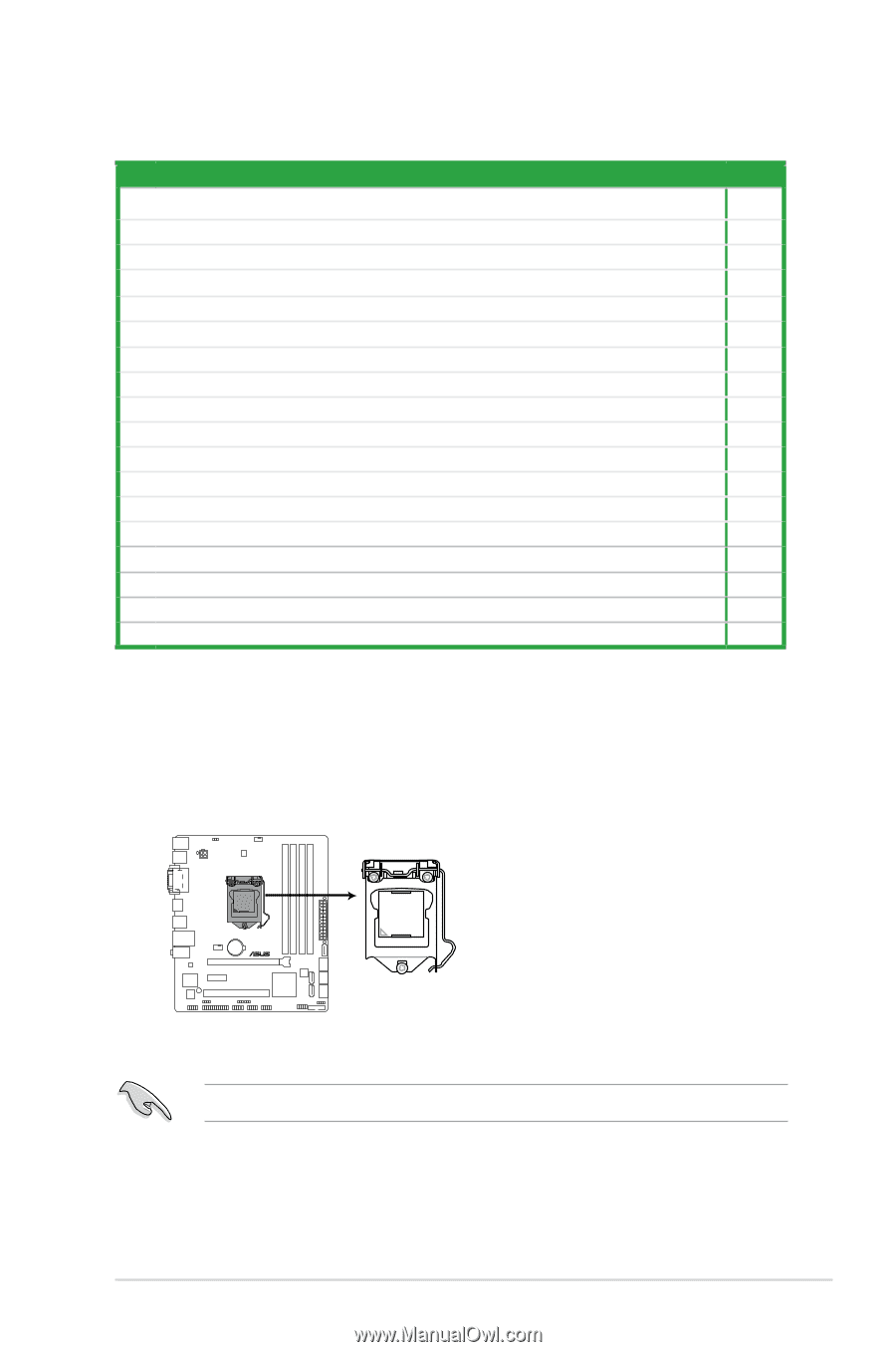
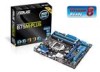
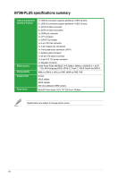
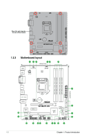
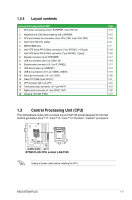
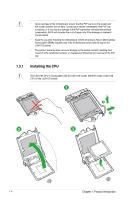
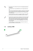
1.2.4 Layout contents Connectors/Jumpers/Slots/LED 1. ATX power connectors (24-pin EATXPWR, 4-pin ATX12V) 2. Keyboard and USB device wake-up (KB_USBPWB) 3. CPU and chassis fan connectors (4-pin CPU_FAN, 4-pin CHA_FAN) 4. Intel® LGA1155 CPU socket 5. DDR3 DIMM slots 6. Intel® B75 Serial ATA 3.0Gb/s connectors (7-pin SATA3G_1~5 [blue]) 7. Intel® B75 Serial ATA 6.0Gb/s connector (7-pin SATA6G_1 [gray]) 8. Speaker connector (4-pin SPEAKER) 9. USB 3.0 connector (20-1 pin USB3_34) 10. System panel connector (10-1 pin F_PANEL) 11. USB device wake-up (USBPWF) 12. USB 2.0 connectors (10-1 pin USB56, USB78) 13. Serial port connectors (10-1 pin COM) 14. Clear RTC RAM (3-pin CLRTC) 15. LPT connector (26-1 pin LPT) 16. Front panel audio connector (10-1 pin AAFP) 17. Digital audio connector (4-1 pin SPDIF_OUT) 18. Onboard LED (SB_PWR) Page 1-15 1-12 1-16 1-3 1-7 1-18 1-18 1-17 1-19 1-17 1-12 1-19 1-20 1-11 1-21 1-15 1-20 1-21 1.3 Central Processing Unit (CPU) This motherboard comes with a surface mount LGA1155 socket designed for the Intel 3rd/2nd generation Core™ i7 / Core™ i5 / Core™ i3 / Pentium® / Celeron® processors. B75M-PLUS B75M-PLUS CPU socket LGA1155 Unplug all power cables before installing the CPU. ASUS B75M-PLUS 1-3
-
 1
1 -
2
-
3
-
4
-
5
-
 6
6 -
 7
7 -
 8
8 -
 9
9 -
 10
10 -
 11
11 -
 12
12 -
 13
13 -
 14
14 -
 15
15 -
 16
16 -
17
-
18
-
19
-
20
-
21
-
22
-
23
-
24
-
25
-
26
-
27
-
28
-
29
-
30
-
31
-
32
-
33
-
34
-
35
-
36
-
37
-
38
-
39
-
40
-
41
-
42
-
43
-
44
-
45
-
46
-
47
-
48
-
49
-
50
-
51
-
52
-
53
-
54
-
55
-
56
-
57
-
58
-
59
-
60
-
61
-
62
-
63
-
64
-
65
-
66
-
67
-
68
-
69
 |
 |