Asus B75M-PLUS B75M-PLUS User's Manual - Page 27
B75M-PLUS USB2.0 connectors, B75M-PLUS USB3.0 Front panel connector
 |
View all Asus B75M-PLUS manuals
Add to My Manuals
Save this manual to your list of manuals |
Page 27 highlights
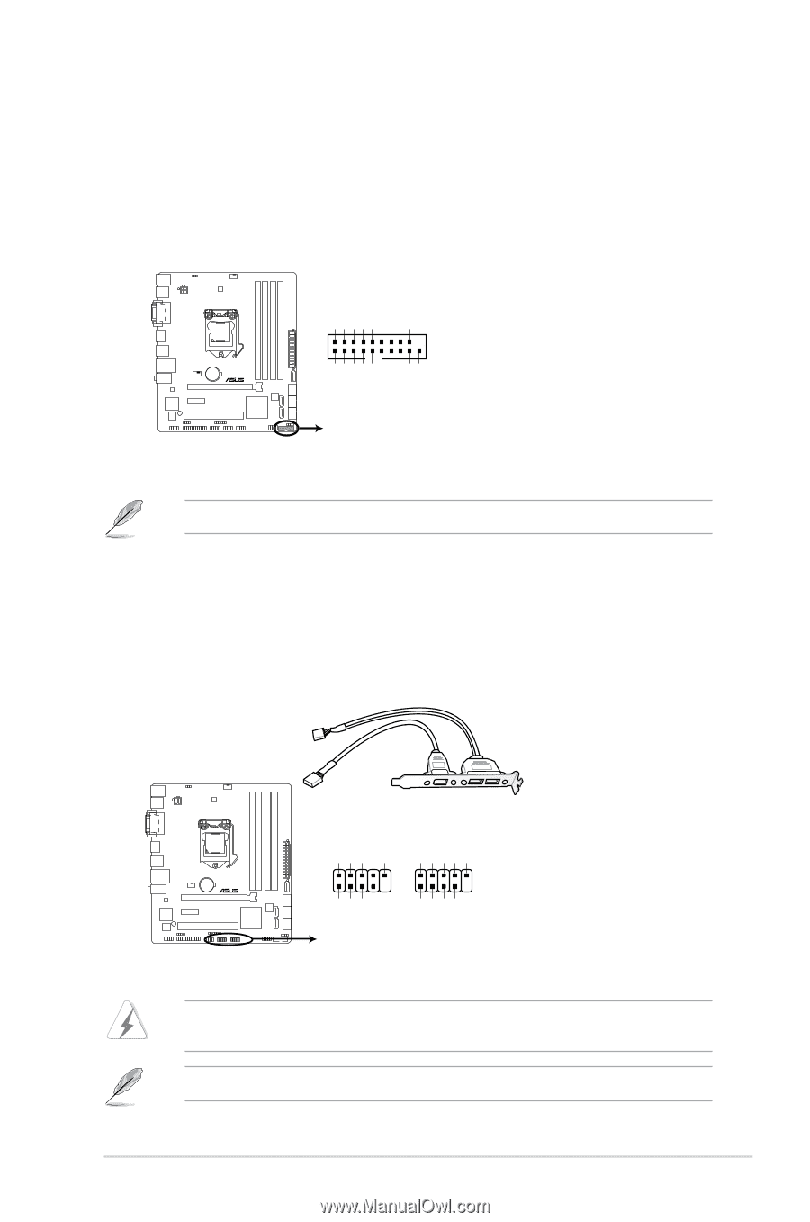
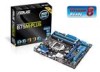
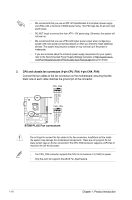
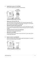
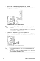
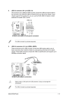
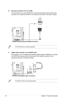
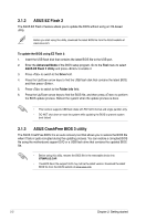
8. USB 3.0 connector (20-1 pin USB3_34) This connector is for additional USB 3.0 ports. Connect the USB 3.0 bracket cable to this connector, then install the USB 3.0 bracket to the rear side of the chassis. If your chassis supports front panel ports, you can use the ASUS USB 3.0 header to install additional front panel USB 3.0 ports. USB3_34 IntA_P2_D+ IntA_P2_DGND IntA_P2_SSTX+ IntA_P2_SSTXGND IntA_P2_SSRX+ IntA_P2_SSRXVbus ID IntA_P1_D+ IntA_P1_D- GND IntA_P1_SSTX+ GND IntA_P1_SSTXIntA_P1_SSRX+ IntA_P1_SSRX- Vbus B75M-PLUS PIN 1 B75M-PLUS USB3.0 Front panel connector The USB 3.0 module is purchased separately. 9. USB 2.0 connectors (10-1 pin USB56, USB78) These connectors are for USB 2.0 ports. Connect the USB module cable to any of these connectors, then install the module to a slot opening at the back of the system chassis. These USB connectors comply with USB 2.0 specifications and supports up to 480Mbps connection speed. USB56 USB78 USB+5V USB_P5USB_P5+ GND NC USB+5V USB_P7USB_P7+ GND NC USB+5V USB_P6USB_P6+ GND USB+5V USB_P8USB_P8+ GND B75M-PLUS PIN 1 PIN 1 PIN 1 B75M-PLUS USB2.0 connectors Never connect a 1394 cable to the USB connectors. Doing so will damage the motherboard! The USB 2.0 module is purchased separately. ASUS B75M-PLUS 1-19
-
 1
1 -
2
-
3
-
4
-
5
-
6
-
7
-
8
-
9
-
10
-
11
-
12
-
13
-
14
-
15
-
16
-
17
-
18
-
19
-
20
-
21
-
 22
22 -
 23
23 -
 24
24 -
 25
25 -
 26
26 -
 27
27 -
 28
28 -
 29
29 -
 30
30 -
 31
31 -
 32
32 -
33
-
34
-
35
-
36
-
37
-
38
-
39
-
40
-
41
-
42
-
43
-
44
-
45
-
46
-
47
-
48
-
49
-
50
-
51
-
52
-
53
-
54
-
55
-
56
-
57
-
58
-
59
-
60
-
61
-
62
-
63
-
64
-
65
-
66
-
67
-
68
-
69
 |
 |