Asus BP5120 User Manual - Page 42
Replacing the supporting stand and, the covers
 |
View all Asus BP5120 manuals
Add to My Manuals
Save this manual to your list of manuals |
Page 42 highlights
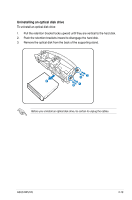
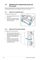
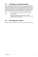
2.7 Replacing the supporting stand and the covers After you have installed all the necessary components on the system, replace the supporting stand and the covers following the instructions in this section. 2.7.1 Replace the supporting stand To replace the supporting stand: B 1. Insert the supporting stand into the tenons (A). 2. Push down the retention bracket locks (B) to secure the supporting stand to the system. A B A 2.7.2 Replace the front panel assembly To replace the front panel assembly: 1. Place the system vertically. Insert the hinge-like tabs on the right edge 1 of the front panel assembly into the holes on the right side of the chassis. 2. Swing the front panel assembly 2 to the left, then insert the hooks to the chassis until the front panel SMC CF MD assembly fits in place. 1 SD MMC MS 2-20 Chapter 2: Basic installation
-
 1
1 -
2
-
3
-
4
-
5
-
6
-
7
-
8
-
9
-
10
-
11
-
12
-
13
-
14
-
15
-
16
-
17
-
18
-
19
-
20
-
21
-
22
-
23
-
24
-
25
-
26
-
27
-
28
-
29
-
30
-
31
-
32
-
33
-
34
-
35
-
36
-
 37
37 -
 38
38 -
 39
39 -
 40
40 -
 41
41 -
 42
42 -
 43
43 -
 44
44 -
 45
45 -
 46
46 -
 47
47 -
48
-
49
-
50
-
51
-
52
-
53
-
54
-
55
-
56
 |
 |
