Asus CUV266 CUV266 User Manual - Page 38
ASUS CUV266 User's Manual, Infrared Module Connector 5-pin IR_CON, UART2 Use Infrared, Chassis Open
 |
View all Asus CUV266 manuals
Add to My Manuals
Save this manual to your list of manuals |
Page 38 highlights
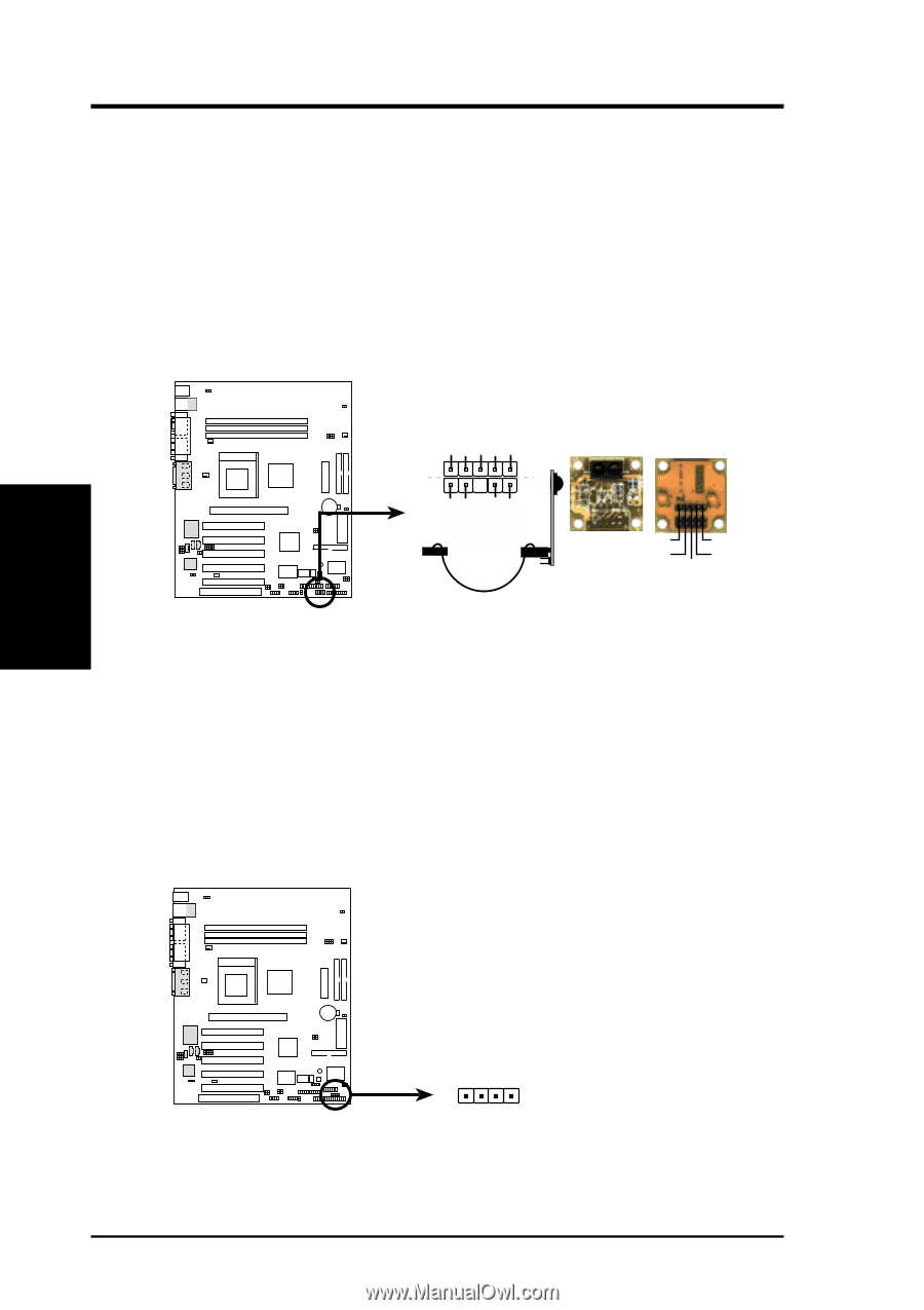
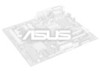
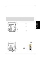
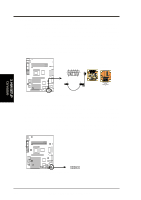
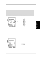
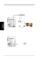
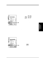
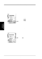
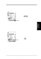
3. HARDWARE SETUP 8) Infrared Module Connector (5-pin IR_CON) This connector supports an optional wireless transmitting and receiving infrared module. This module mounts to a small opening on system cases that support this feature. You must also configure the setting through UART2 Use Infrared (see 4.4.2 I/O Device Configuration) to select whether UART2 is directed for use with COM2 or IrDA. Use the five pins as shown in Back View and connect a ribbon cable from the module to the motherboard SIR connector according to the pin definitions. (NOTE: The SIR module does not come with the motherboard package. The CIR module is currently not available.) 01 01 01 +5V (NC) IRRX GND IRTX CUV266 Standard Infrared (SIR) Front View Back View SIR CIR CIRTX GND CIRRX CIR+5V IRTX +5V GND (NC) IRRX CUV266 Infrared Module Connector 9) Chassis Open Alarm Lead (4-pin CHASSIS) This lead is for a chassis designed for chassis intrusion detection. This requires an external detection mechanism such as a chassis intrusion monitor/sensor or microswitch. When any chassis component is removed, the sensor is triggered and a high-level signal is sent to this lead to record a chassis intrusion event.The event is then be processed by software such as LDCM. When not using the chassis intrusion lead, place a jumper cap over the pins to close the circuit. CUV266 3. H/W SETUP Connectors 01 01 01 CHASSIS CUV266 Chassis Open Alarm Lead 38 ASUS CUV266 User's Manual
-
 1
1 -
2
-
3
-
4
-
5
-
6
-
7
-
8
-
9
-
10
-
11
-
12
-
13
-
14
-
15
-
16
-
17
-
18
-
19
-
20
-
21
-
22
-
23
-
24
-
25
-
26
-
27
-
28
-
29
-
30
-
31
-
32
-
 33
33 -
 34
34 -
 35
35 -
 36
36 -
 37
37 -
 38
38 -
 39
39 -
 40
40 -
 41
41 -
 42
42 -
 43
43 -
44
-
45
-
46
-
47
-
48
-
49
-
50
-
51
-
52
-
53
-
54
-
55
-
56
-
57
-
58
-
59
-
60
-
61
-
62
-
63
-
64
-
65
-
66
-
67
-
68
-
69
-
70
-
71
-
72
-
73
-
74
-
75
-
76
-
77
-
78
-
79
-
80
-
81
-
82
-
83
-
84
-
85
-
86
-
87
-
88
-
89
-
90
-
91
-
92
-
93
-
94
-
95
-
96
-
97
-
98
-
99
-
100
-
101
-
102
-
103
-
104
 |
 |