Asus DVD-E616P2 English User Manual - Page 17
Refer to for jumper settings.
 |
View all Asus DVD-E616P2 manuals
Add to My Manuals
Save this manual to your list of manuals |
Page 17 highlights
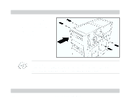
Pin 1 2 & 3 4 Name L G R Description Left channel audio output Ground Right channel audio output 7. Device configuration jumper These pins allow you to select either Master, Slave, or Cable Select mode for the DVD-ROM device. (Refer to page 18 for jumper settings.) Pin Name Switch Status Description 1 MA ON Master mode 2 SL ON Slave mode 3 CS ON Cable select mode 8. Host IDE interface This connector is for a 40-pin IDE cable to connect the drive to the IDE interface on the motherboard. 9. DC input This DC connector is for a 4-pin power cable from the system power supply. ASUS DVD-E616P2 17
-
 1
1 -
2
-
3
-
4
-
5
-
6
-
7
-
8
-
9
-
10
-
11
-
 12
12 -
 13
13 -
 14
14 -
 15
15 -
 16
16 -
 17
17 -
 18
18 -
 19
19 -
 20
20 -
 21
21 -
 22
22 -
23
-
24
-
25
-
26
-
27
-
28
-
29
-
30
-
31
-
32
-
33
-
34
 |
 |
ASUS DVD-E616P2
17
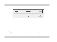
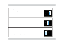
7.
Device configuration jumper
These pins allow you to select either Master, Slave, or Cable Select
mode for the DVD-ROM device. (
Refer to page 18 for jumper settings.
)
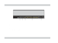
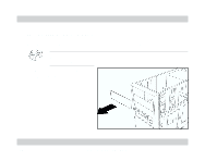
8. Host IDE in
terface
This connector is for a 40-pin IDE cable to connect the drive to the IDE
interface on the motherboard.
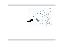
9. DC input
This DC connector is for a 4-pin power cable from the system power supply.
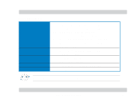
Pin
Name
Switch Status
Description
1
MA
ON
Master mode
2
SL
ON
Slave mode
3
CS
ON
Cable select mode
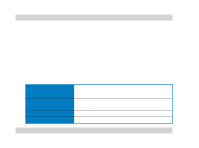
Pin
Name
Description
1
L
Left channel audio output
2 & 3
G
Ground
4
R
Right channel audio output