Asus E3-PRO V5 E3-PRO V5 Users manual English - Page 12
To erase the RTC RAM, System panel connector 20-5 pin F_PANEL, Clear RTC RAM 2-pin CLRTC
 |
View all Asus E3-PRO V5 manuals
Add to My Manuals
Save this manual to your list of manuals |
Page 12 highlights
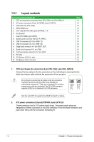
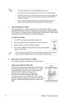
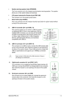
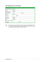
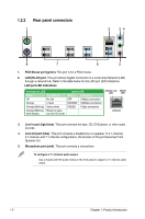
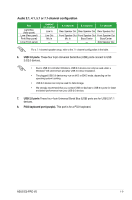
• This socket supports M Key and 2242/2260/2280 storage devices. • When the M.2 Socket 3 is operating in SATA mode, SATA port 1 will be disabled. • M.2 Socket and PCIe X16_2 connector support PCIe mode and share bandwidth. By default, the device detection priority of the system is as follows: SATA Mode M.2 > PCIe X16_2 connector. • When using Intel® Desktop Responsiveness technologies with PCIe M.2 device, ensure to set up the Windows® UEFI operating system under RAID mode. 7. Clear RTC RAM (2-pin CLRTC) This header allows you to clear the Real Time Clock (RTC) RAM in CMOS. You can clear the CMOS memory of date, and system setup parameters by erasing the CMOS RTC RAM data. The onboard button cell battery powers the RAM data in CMOS, which include system setup information such as system passwords. To erase the RTC RAM: 1. Turn OFF the computer and unplug the power cord. 2. Use a metal object such as a screwdriver to short the two pins. 3. Plug the power cord and turn ON the computer. 4. Hold down the key during the boot process and enter BIOS setup to re-enter data. +3V_BAT GND CLRTC PIN 1 If the steps above do not help, remove the onboard battery and short the two pins again to clear the CMOS RTC RAM data. After clearing the CMOS, reinstall the battery. 8. System panel connector (20-5 pin F_PANEL) This connector supports several chassis-mounted functions. • System power LED (4-pin PWR_LED) PANEL This 4-pin connector is for the system power LED. Connect +PWR_LED- PWR_SW SPEAKER the chassis power LED cable to this connector. The system power LED lights up when you turn on the system power, and blinks when the system is in sleep mode. PLED+ PLEDPWRBTN# GND +5V GND GND Speaker • Hard disk drive activity LED (2-pin HDD_LED) HDD_LED+ HDD_LED- GND RSTCON# NC PLED+ PLED- PIN 1 This 2-pin connector is for the HDD Activity LED. Connect the HDD Activity LED cable to this connector. The HDD LED lights up or flashes when data is read from or written to the HDD. +HDD_LED- RESET +PWR_LED- * Requires an ATX power supply 1-4 Chapter 1: Product introduction
-
 1
1 -
2
-
3
-
4
-
5
-
6
-
 7
7 -
 8
8 -
 9
9 -
 10
10 -
 11
11 -
 12
12 -
 13
13 -
 14
14 -
 15
15 -
 16
16 -
 17
17 -
18
-
19
-
20
-
21
-
22
-
23
-
24
-
25
-
26
-
27
-
28
-
29
-
30
-
31
-
32
-
33
-
34
-
35
-
36
 |
 |
