Asus E3-PRO V5 E3-PRO V5 Users manual English - Page 14
PCI Express 3.0/2.0 x16 slots, PCI slots, Front panel audio connector 10-1 pin AAFP
 |
View all Asus E3-PRO V5 manuals
Add to My Manuals
Save this manual to your list of manuals |
Page 14 highlights
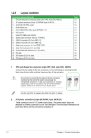
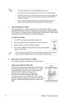
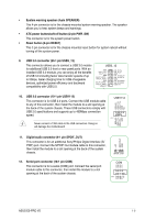
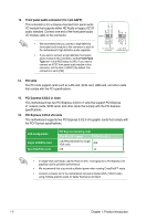
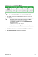
13. Front panel audio connector (10-1 pin AAFP) AGND NC SENSE1_RETUR SENSE2_RETUR This connector is for a chassis-mounted front panel audio I/O module that supports either HD Audio or legacy AC`97 audio standard. Connect one end of the front panel audio I/O module cable to this connector. AAFP PIN 1 AGND NC NC NC MIC2 MICPWR Line out_R NC Line out_L PORT1 L PORT1 R PORT2 R SENSE_SEND PORT2 L • We recommend that you connect a high-definition front panel audio module to this connector to avail of the motherboard's high-definition audio capability. • If you want to connect a high-definition front panel audio module to this connector, set the Front Panel Type item in the BIOS setup to [HD]. If you want to connect an AC'97 front panel audio module to this connector, set the item to [AC97]. By default, this connector is set to [HD]. HD-audio-compliant Legacy AC'97 pin definition compliant definition 14. PCI slots The PCI slots support cards such as LAN card, SCSI card, USB card, and other cards that comply with the PCI specifications. 15. PCI Express 3.0/2.0 x1 slots This motherboard has two PCI Express 3.0/2.0 x1 slots that support PCI Express x1 network cards, SCSI cards, and other cards that comply with the PCI Express specifications. 16. PCI Express 3.0/2.0 x16 slots This motherboard supports two PCI Express 3.0/2.0 x16 graphic cards that comply with the PCI Express specifications. VGA configuration Single VGA/PCIe card Dual VGA/PCIe cards PCI Express operating mode PCIe 3.0 x16_1 (gray) PCIe 3.0 x16_2 x16 (Recommended for single VGA card) N/A x16 x4 • In single VGA card mode, use the PCIe 3.0 x16_1 slot (gray) for a PCI Express x16 graphics card to get better performance. • We recommend that you provide sufficient power when running CrossFireX™ mode. • Connect a chassis fan to the motherboard connector labeled CHA_FAN1/2 when using multiple graphics cards for better thermal environment. 1-6 Chapter 1: Product introduction
-
 1
1 -
2
-
3
-
4
-
5
-
6
-
7
-
8
-
 9
9 -
 10
10 -
 11
11 -
 12
12 -
 13
13 -
 14
14 -
 15
15 -
 16
16 -
 17
17 -
 18
18 -
 19
19 -
20
-
21
-
22
-
23
-
24
-
25
-
26
-
27
-
28
-
29
-
30
-
31
-
32
-
33
-
34
-
35
-
36
 |
 |
