Asus ET1610P User Manual - Page 22
English, removed in the previous step noting
 |
View all Asus ET1610P manuals
Add to My Manuals
Save this manual to your list of manuals |
Page 22 highlights
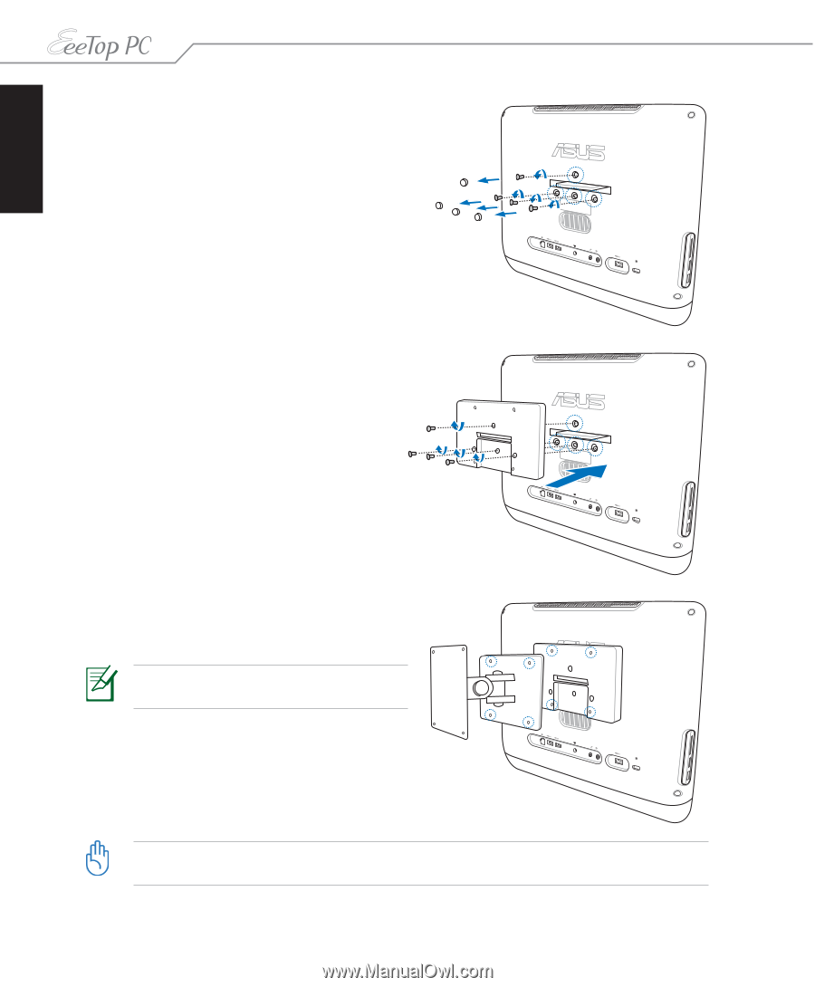
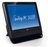
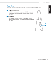
English 2. Take out the four rubber items in the panel holes, and then remove the four screws from the panel. Keep the screws for later use. 3. Secure the wall mount pad to the rear panel with the four screws (M3 x 8L) you removed in the previous step noting the correct orientation. 4. Install your wall mount kit (VESA75) to the wall mount pad using four screws (M4 x 10L) that came with the wall mount kit package. The wall mount kit in this illustration is for reference only. 5. Fasten the wall mount kit to the wall following the instructions described in the installation manual that came with your wall mount kit package. For ventilation's sake, ensure that you leave a distance of 6cm at least between the system and the wall. 22 EeeTop PC ET16 Series
-
 1
1 -
2
-
3
-
4
-
5
-
6
-
7
-
8
-
9
-
10
-
11
-
12
-
13
-
14
-
15
-
16
-
 17
17 -
 18
18 -
 19
19 -
 20
20 -
 21
21 -
 22
22 -
 23
23 -
 24
24 -
 25
25 -
 26
26 -
 27
27 -
28
-
29
-
30
-
31
-
32
-
33
-
34
-
35
-
36
 |
 |