Asus H81I-PLUS H81I-PLUS User's Manual - Page 26
Onboard LEDs, H81I-PLUS Onboard LED
 |
View all Asus H81I-PLUS manuals
Add to My Manuals
Save this manual to your list of manuals |
Page 26 highlights
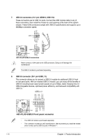
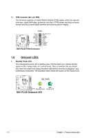
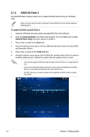
11. TPM connector (20-1 pin TPM) This connector supports a Trusted Platform Module (TPM) system, which can securely store keys, digital certificates, passwords and data. A TPM system also helps enhance network security, protects digital identities and ensures platform integrity. TPM H81I-PLUS RESET GPIO SERIRQ SMBSDA GND LAD1 LAD2 PWROWN GND SB_SUS_STAT GND +3VSB SMBSCL LAD0 +3V LAD3 PCIRST# FRAME PCICLK PIN 1 H81I-PLUS TPM Connector 1.8 Onboard LEDs 1. Standby Power LED The motherboard comes with a standby power LED that lights up to indicate that the system is ON, in sleep mode, or in soft-off mode. This is a reminder that you should shut down the system and unplug the power cable before removing or plugging in any motherboard component. The illustration below shows the location of the onboard LED. SB_PWR H81I-PLUS ON OFF Standby Power Powered Off H81I-PLUS Onboard LED 1-18 Chapter 1: Product introduction
-
 1
1 -
2
-
3
-
4
-
5
-
6
-
7
-
8
-
9
-
10
-
11
-
12
-
13
-
14
-
15
-
16
-
17
-
18
-
19
-
20
-
 21
21 -
 22
22 -
 23
23 -
 24
24 -
 25
25 -
 26
26 -
 27
27 -
 28
28 -
 29
29 -
 30
30 -
 31
31 -
32
-
33
-
34
-
35
-
36
-
37
-
38
-
39
-
40
-
41
-
42
-
43
-
44
-
45
-
46
-
47
-
48
-
49
-
50
-
51
-
52
-
53
-
54
-
55
-
56
-
57
-
58
-
59
-
60
-
61
-
62
-
63
-
64
-
65
-
66
-
67
-
68
-
69
-
70
-
71
-
72
-
73
-
74
 |
 |
