Asus K8V-MX K8V-MX User's Manual for English Edition - Page 32
Product Introduction, IDE connectors 40-1 pin PRI_IDE, SEC_IDE, Digital audio connector 3
 |
View all Asus K8V-MX manuals
Add to My Manuals
Save this manual to your list of manuals |
Page 32 highlights
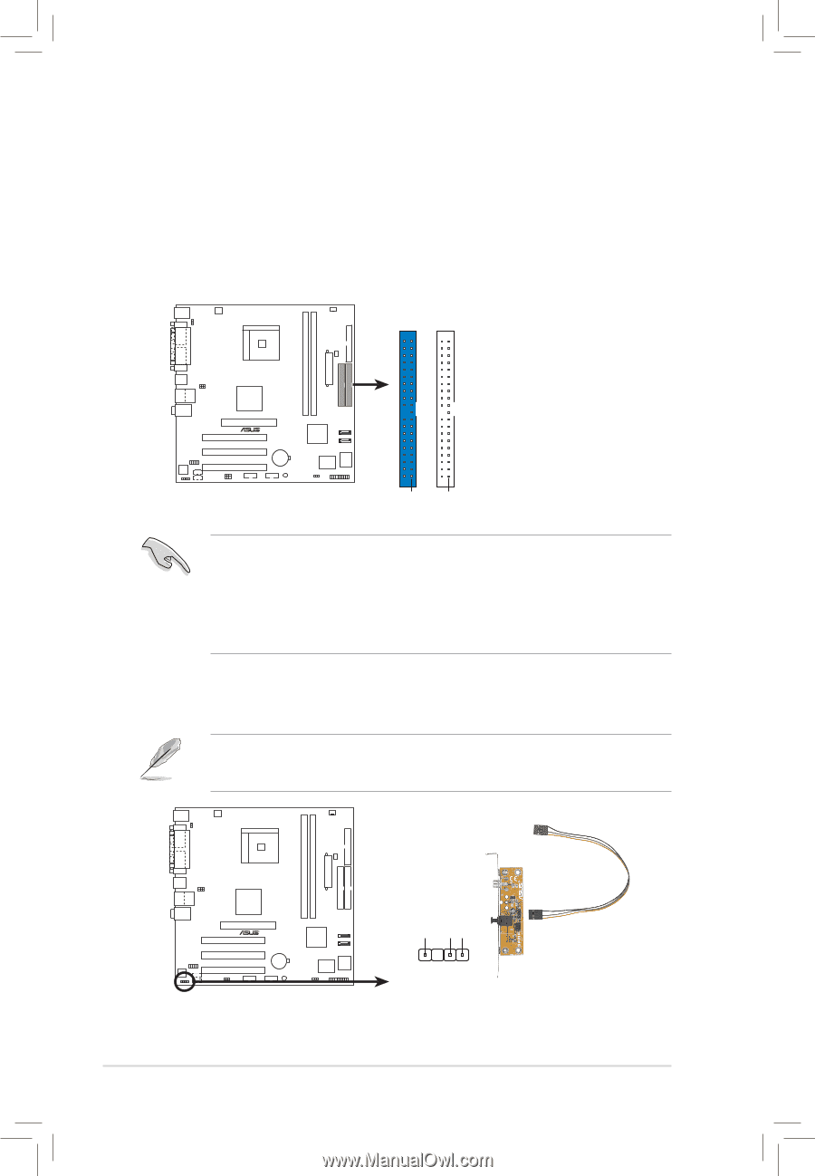
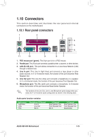
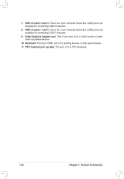
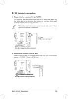
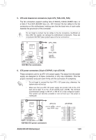
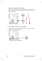
3. IDE connectors (40-1 pin PRI_IDE, SEC_IDE) These connectors support the provided Ultra ATA/133 IDE hard disk ribbon cable. Connect the cableʼs blue connector to the primary (recommended) or secondary IDE connector, then connect the gray connector to the Ultra ATA/133 slave device (hard disk drive) and the black connector to the Ultra ATA/133 master device. Connecting non-Ultra ATA/133 devices to the secondary IDE connector is recommended. PRI_IDE SEC_IDE R K8V-MX NOTE: Orient the red markings (usually zigzag) on the IDE ribbon cable to PIN 1. K8V-MX IDE connectors PIN 1 PIN 1 • Pin 20 on each IDE connector is removed to match the covered hole on the Ultra ATA cable connector. This prevents incorrect orientation when you connect the cables. • For Ultra ATA/133 IDE devices, use an 80-conductor IDE cable. • The hole near the blue connector on the Ultra ATA/133 cable is intentional. 4. Digital audio connector (3- pin SPDIF) This connector is for the S/PDIF audio module that allows digital sound input. • Use 75 ohm impedance matched coaxial cables for your S/PDIF connection. • The S/PDIF module is purchased separately. +5V SPDIFOUT GND R K8V-MX SPDIF_OUT K8V-MX Digital audio connector 1-22 Chapter 1: Product Introduction
-
 1
1 -
2
-
3
-
4
-
5
-
6
-
7
-
8
-
9
-
10
-
11
-
12
-
13
-
14
-
15
-
16
-
17
-
18
-
19
-
20
-
21
-
22
-
23
-
24
-
25
-
26
-
 27
27 -
 28
28 -
 29
29 -
 30
30 -
 31
31 -
 32
32 -
 33
33 -
 34
34 -
 35
35 -
 36
36 -
 37
37 -
38
-
39
-
40
-
41
-
42
-
43
-
44
-
45
-
46
-
47
-
48
-
49
-
50
-
51
-
52
-
53
-
54
-
55
-
56
-
57
-
58
-
59
-
60
-
61
-
62
-
63
-
64
-
65
-
66
-
67
-
68
-
69
-
70
-
71
-
72
 |
 |