Asus MAXIMUS VI HERO MAXIMUS VI HERO User's Manual
Asus MAXIMUS VI HERO Manual
 |
View all Asus MAXIMUS VI HERO manuals
Add to My Manuals
Save this manual to your list of manuals |
Asus MAXIMUS VI HERO manual content summary:
- Asus MAXIMUS VI HERO | MAXIMUS VI HERO User's Manual - Page 1
Motherboard MAXIMUS VI HERO - Asus MAXIMUS VI HERO | MAXIMUS VI HERO User's Manual - Page 2
ASUS. ASUS ASSUMES NO RESPONSIBILITY OR LIABILITY FOR ANY ERRORS OR INACCURACIES THAT MAY APPEAR IN THIS MANUAL from http://support.asus.com/download code as required under various Free Open Source Software licenses. If however you encounter any problems in obtaining the full corresponding source code - Asus MAXIMUS VI HERO | MAXIMUS VI HERO User's Manual - Page 3
CPU installation 2-3 2.1.3 CPU heatsink and fan assembly installation 2-4 2.1.4 DIMM installation 2-6 2.1.5 ATX Power connection 2-7 2.1.6 SATA device connection 2-8 2.1.7 Front I/O Connector 2-9 2.1.8 Expansion Card installation 2-10 2.2 BIOS update utility 2-11 2.3 Motherboard - Asus MAXIMUS VI HERO | MAXIMUS VI HERO User's Manual - Page 4
3.8 Boot menu 3-42 3.9 Tools menu 3-47 3.9.1 ASUS EZ Flash 2 Utility 3-47 3.9.2 ROG Secure Erase 3-47 3.9.3 ASUS O.C. Profile 3-49 3.9.4 ASUS SPD Information 3-50 3.9.5 ROG OC Panel H-Key Configure 3-50 3.10 Exit menu 3-52 3.11 Updating BIOS 3-53 3.11.1 EZ Update 3-53 3.11.2 ASUS - Asus MAXIMUS VI HERO | MAXIMUS VI HERO User's Manual - Page 5
4.2.1 Running the support DVD 4-1 4.2.2 Obtaining the software manuals 4-2 4.3 Software information 4-3 4.4 AI Suite 3...4-3 4.4.1 Dual Intelligent Processors 4 4-6 4.4.2 EZ Update 4-13 4.4.3 USB 3.0 Boost 4-14 4.4.4 System Information 4-15 4.4.5 USB BIOS Flashback 4-17 4.4.6 USB - Asus MAXIMUS VI HERO | MAXIMUS VI HERO User's Manual - Page 6
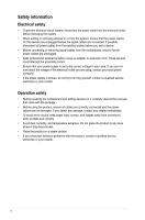
removing signal cables from the motherboard, ensure that all power service technician or your retailer. Operation safety • Before installing the motherboard and adding devices on it, carefully read all the manuals problems with the product, contact a qualified service technician or your retailer - Asus MAXIMUS VI HERO | MAXIMUS VI HERO User's Manual - Page 7
of the support DVD that comes with the motherboard package and the software. • Chapter 5: RAID support This chapter describes the RAID configurations. Where to find more information Refer to the following sources for additional information and for product and software updates. 1. ASUS websites The - Asus MAXIMUS VI HERO | MAXIMUS VI HERO User's Manual - Page 8
note of the following symbols used throughout this manual. DANGER/WARNING: Information to prevent injury to yourself when trying to complete a task. CAUTION: Information to prevent damage to the components when trying to complete a task IMPORTANT: Instructions that you MUST follow to complete a task - Asus MAXIMUS VI HERO | MAXIMUS VI HERO User's Manual - Page 9
MAXIMUS VI HERO specifications summary CPU Chipset Memory Expansion slots VGA Multi-GPU support Storage LGA1150 socket for 4th Generation Intel® Core™ i7/ i5/ i3/ Pentium®/ Celeron® processors Supports 22nm CPU Supports Intel® Turbo Boost Technology 2.0* * The Intel® Turbo Boost Technology 2.0 - Asus MAXIMUS VI HERO | MAXIMUS VI HERO User's Manual - Page 10
at mid-board**) * Supports ASUS USB3.0 Boost, UASP standard on the Intel® native USB 3.0 is only supported under Windows® 8. ** 2 x USB2.0 ports at mid-board shares with ROG extension (ROG_EXT) port. 1 xPS/2 keyboard/mouse combo port 4 x USB 2.0 ports 1 x USB BIOS Flashback button 1 x Optical S/PDIF - Asus MAXIMUS VI HERO | MAXIMUS VI HERO User's Manual - Page 11
AI Charger - Disk Unlocker ASUS EZ DIY - USB BIOS Flashback - ASUS CrashFree BIOS 3 - ASUS EZ Flash 2 - ASUS C.P.R. (CPU Parameter Recall) ASUS Q-Design - ASUS Q-Code - ASUS Q-Shield - ASUS Q-Connector - ASUS Q-LED (CPU, DRAM, VGA, Boot Device LED) - ASUS Q-Slot - ASUS Q-DIMM (continued on the next - Asus MAXIMUS VI HERO | MAXIMUS VI HERO User's Manual - Page 12
64 Mb UEFI AMI BIOS, PnP, DMI 2.0, WfM 2.0, SM BIOS 2.5, ACPI 2.0a, Multi-language BIOS WfM2.0, DMI2.0, WOL by PME, PXE Drivers ROG GameFirst II ROG RAMDisk ROG CPU-Z ROG Mem TweakIt Kaspersky® Anti-Virus DAEMON Tools Pro Standard ASUS WebStorage ASUS Utilities ATX Form Factor, 12" x 9.6" (30 - Asus MAXIMUS VI HERO | MAXIMUS VI HERO User's Manual - Page 13
for the following items. Motherboard Cables Accessories Application DVD Documentation ROG MAXIMUS VI HERO 3 x 2-in-1 SATA 6 Gb/s cables 1 x SLI® bridge I/O Shield 1 x 12-in-1 ROG cable label 1 x 2-in-1 Q-Connector kit 1 x ROG Door Hanger ROG motherboard support DVD User guide If any of the above - Asus MAXIMUS VI HERO | MAXIMUS VI HERO User's Manual - Page 14
(cross) screwdriver PC chassis Power supply unit Intel LGA 1150 CPU Intel LGA 1150 compatible CPU Fan DDR3 DIMM SATA hard disk drive SATA optical disc drive (optional) Graphics card (optional) The tools and components in the table above are not included in the motherboard package. xiv - Asus MAXIMUS VI HERO | MAXIMUS VI HERO User's Manual - Page 15
unique PCIe 3.0 bridge chip to support multi-GPU SLI®/ CrossFireX™ graphics cards for an unrivaled gaming performance. With the Intel® Z87 platform to optimize the PCIe allocation of multiple GPUs, it supports up to 4-WAY GPU SLI® or CrossFireX™ configuration�. Chapter 1 ASUS MAXIMUS VI HERO 1-1 - Asus MAXIMUS VI HERO | MAXIMUS VI HERO User's Manual - Page 16
attractive look for the motherboard in keeping with ROG via chat. Discover a whole new dimension of superior audio and get ready Intel Gigabit LAN The LAN solution from Intel has been long known to have a better throughput, lower CPU utilization as well as better stability. With the Intel Gigabit LAN - Asus MAXIMUS VI HERO | MAXIMUS VI HERO User's Manual - Page 17
BIOS or the operating system, just plug the thumb drive into the ROG Connect port & push the ROG Connect button for 3 seconds, BIOS would be automatically flashed under standby power. It's no doubt that USB BIOS Flashback gives overclockers the ultimate convenience! Chapter 1 ASUS MAXIMUS VI HERO - Asus MAXIMUS VI HERO | MAXIMUS VI HERO User's Manual - Page 18
Blu-ray discs. It converts optical media into virtual discs and emulates devices to work with the virtual copies. DAEMON Tools Pro organizes data, music, video, and photo collections on a PC, notebook, or netbook. ROG CPU-Z ROG CPU-Z is a customized ROG version authorized by CPUID. It has the same - Asus MAXIMUS VI HERO | MAXIMUS VI HERO User's Manual - Page 19
came with the component. • Before you install or remove any component, ensure that the ATX power supply is switched off or the power cord is detached from the power supply. Failure to do so may cause severe damage to the motherboard, peripherals, or components. Chapter 1 ASUS MAXIMUS VI HERO 1-5 - Asus MAXIMUS VI HERO | MAXIMUS VI HERO User's Manual - Page 20
1.2.2 Motherboard layout Chapter 1 Refer to 1.2.9 Internal connectors and 2.3.1 Rear I/O connection for more information about rear panel connectors and internal connectors. 1-6 Chapter 1: Product introduction - Asus MAXIMUS VI HERO | MAXIMUS VI HERO User's Manual - Page 21
; 8-pin EATX12V) 2. CPU, chassis, and optional fan connectors (4-pin CPU_FAN; 4-pin CPU_OPT; 4-pin CHA_FAN1-3) 3. LGA1150 CPU Socket 4. DDR3 DIMM slots 5. Q_Code LEDs 6. MemOK! button 7. START (Power-on) button 8. RESET button 9. USB 3.0 connectors (20-1 pin USB3_12) 10. Intel® Z87 Serial ATA 6 Gb - Asus MAXIMUS VI HERO | MAXIMUS VI HERO User's Manual - Page 22
Unit (CPU) The motherboard comes with a surface mount LGA1150 socket designed for the 4th Generation Intel® Core™ i7 / Intel® Core™ i5 / Intel® Core™ or if you see any damage to the PnP cap/socket contacts/motherboard components. ASUS will shoulder the cost of repair only if the damage is shipment/ - Asus MAXIMUS VI HERO | MAXIMUS VI HERO User's Manual - Page 23
memory The motherboard comes with four Double Data Rate 3 (DDR3) Dual Inline Memory Modules (DIMM) slots. A DDR3 module is notched differently from a DDR or DDR2 module. DO NOT install a DDR or DDR2 memory module to the DDR3 slot. Recommended memory configurations Chapter 1 ASUS MAXIMUS VI HERO - Asus MAXIMUS VI HERO | MAXIMUS VI HERO User's Manual - Page 24
Microsoft® support site at http://support.microsoft. com/kb/929605/en-us. • This motherboard does not support DIMMs made up of 512Mb (64MB) chips or less (Memory chip capacity section 3.4 Extreme Tweaker menu for manual memory frequency adjustment. F�o�r��s�y�s�t�e�m��s��ta�b��il�it - Asus MAXIMUS VI HERO | MAXIMUS VI HERO User's Manual - Page 25
MAXIMUS VI HERO Motherboard Qualified Vendors Lists (QVL) DDR3 2800 MHz capability Vendors Part No. Size SS/ Chip Chip Timing Voltage DS Brand NO. AVEXIR AVD3U28001204G-4CI 16GB ( 4x 4GB ) DS - - 12-14-14-35 1. - Asus MAXIMUS VI HERO | MAXIMUS VI HERO User's Manual - Page 26
Size SS/ Chip Chip Timing DS Brand NO. G.SKILL F3-20000CL10Q-16GBZHD(XMP) 16GB ( 4x 4GB ) DS - - 10-11-11-31 Voltage 1.65 DIMM socket support (Optional) 2 4 • • DDR3 2400 MHz capability Vendors Part No. Size A-DATA A-DATA Apacer Apacer CORSAIR CORSAIR CORSAIR G.SKILL G.SKILL G.SKILL - Asus MAXIMUS VI HERO | MAXIMUS VI HERO User's Manual - Page 27
- Chip Timing NO. - 7-10-10-28 - 9-10-9-28 - 9-11-9-28 Voltage 1.65 1.65 1.65 DIMM socket support (Optional) 2 4 • • • • • DDR3 2133 MHz capability Vendors Part No - 1.5 • • 11-27 - 11-11-11-31 1.65 • • DS - - 11-11-11-31 1.65 • • ASUS MAXIMUS VI HERO 1-13 Chapter 1 - Asus MAXIMUS VI HERO | MAXIMUS VI HERO User's Manual - Page 28
DDR3 2000 MHz capability Vendors Part No. Size SS/ Chip DS (XMP) TXD32048M2000C9-L 2GB DS (XMP) Hynix Team Team Team Chip NO. - Timing - Voltage DIMM socket support (Optional) 24 1.65 • • - - 1.65 • • - 9-9-9-27 - H5TQ2G83BFRH9C 9-9-9-27 - • • • • - 9-9-9-24 1.65 - Asus MAXIMUS VI HERO | MAXIMUS VI HERO User's Manual - Page 29
1866 9-10- 1.5 • • 9-27 Team TED34G1866HC13BK 4GB SS - - - - • • Team TED38G1866HC-13BK 8GB DS - - - - • • Team TLD34G1866HC9KBK(XMP) 4GB DS - - 9-11-9-27 1.5 • • Team TLD38G1866HC10SBK(XMP) 8GB DS - - 10-11-10-30 1.5 • • Chapter 1 ASUS MAXIMUS VI HERO 1-15 - Asus MAXIMUS VI HERO | MAXIMUS VI HERO User's Manual - Page 30
/ Chip Chip Timing DS Brand NO. G.SKILL F3-14400CL9D-4GBRL(XMP) 4GB ( 2x 2GB ) DS - - 9-9-9-24 Voltage 1.65 DIMM socket support (Optional) 2 4 • • DDR3 1600 MHz capability Vendors A-DATA A-DATA A-DATA A-DATA A-DATA A-DATA A-DATA AMD AMD AMD Apacer Apacer Apacer Apacer Apacer Asint Asint - Asus MAXIMUS VI HERO | MAXIMUS VI HERO User's Manual - Page 31
DDR3 Memory EKM324L28BP8-I16 (XMP) 4GB DS - (2x2GB ) EK Memory Timing 9-9-9-24 Voltage 1.5 DIMM socket support (Optional) 2 4 • - • • - 10-10-10-27 1.5 • • - 9-9-9-24 1.5 • • - 10-10-10-27 1.5 • 24 1.35 • (continued on the next page) Chapter 1 ASUS MAXIMUS VI HERO 1-17 - Asus MAXIMUS VI HERO | MAXIMUS VI HERO User's Manual - Page 32
DDR3 1600 MHz capability Vendors Part No. Size SS/ Chip DS - - H5TQ2G83CFRPBC - - - D9PBC - (continued on the next page) Voltage 1.5 DIMM socket support (Optional) 2 4 • • 1.25 • • 1.5 • • 1.5 • • 1.5 • • 1.6 • • 1.6 • • - • • - • • - • • 1.65 • • 1. - Asus MAXIMUS VI HERO | MAXIMUS VI HERO User's Manual - Page 33
DDR3 K4B4G0846B SAMSUNG K4B4G0846B 11-11-1128-1 11-11-1128-2 Voltage - DIMM socket support (Optional) 2 4 • • - • • - • • - • 1.65 • • - • • - • • 1.5 • • - • • 1.5 • • 1.5 • • 1.5 • • - • • - • • - • • - • • Chapter 1 ASUS MAXIMUS VI HERO 1-19 - Asus MAXIMUS VI HERO | MAXIMUS VI HERO User's Manual - Page 34
DDR3 1333 CORSAIR CMV8GX3M2A1333C9 CORSAIR CORSAIR CORSAIR EK Memory G.SKILL CMX8GX3M1A1333C9 (Ver2.2) CMX8GX3M1A1333C9 ( - - - - Timing 9 9 9-1010-26 9-9-9-24 - 9-9-9-24 9-9-9-24 9-9-9-24 9-9-9-24 9-9-9-24 9 9-9-9-24 9-9-9-24 9-9-9-24 9-9-9-24 9-9-9-24 Voltage DIMM socket support (Optional - Asus MAXIMUS VI HERO | MAXIMUS VI HERO User's Manual - Page 35
DDR3 1333 MHz capability Vendors Part No. Size SS/ Chip Brand Chip NO. DS Timing Voltage DIMM socket support (Optional) 24 GEIL DS - - (2x4GB) 9-9-9 1.65 • Patriot PG38G1333EL(XMP) 8GB DS - - - 1.5 •• (continued on the next page) Chapter 1 ASUS MAXIMUS VI HERO 1-21 - Asus MAXIMUS VI HERO | MAXIMUS VI HERO User's Manual - Page 36
the red and black slots as two pairs of Dual-channel memory configuration. • ASUS exclusively provides hyper DIMM support function. H�y�p��e�r�D��IM��M���s�u�p�p�o��rt�i�s��s�u�b�j�e�c�t�t�o��th��e�p��h�y�s�ic��a�l�c�h�a�r�a�c�t�e�r�is��ti�c�s�o��f�in��d�iv�i�d�u�a��l �C�P��U�s�.��L�o�a�d� the - Asus MAXIMUS VI HERO | MAXIMUS VI HERO User's Manual - Page 37
. Failure to do so may cause you physical injury and damage motherboard components. Chapter 1 Slot No. 1 2 3 4 5 6 Slot Description PCIe 2.0 x1_1 slot PCIe 3.0/2.0 x16/x8_1 slot PCIe 2.0 x1_2 slot PCIe 3.0/2.0 x16/x8_2 slot PCIe 2.0 x1_3 slot PCIe 3.0/2.0 x4_3 slot ASUS MAXIMUS VI HERO 1-23 - Asus MAXIMUS VI HERO | MAXIMUS VI HERO User's Manual - Page 38
thermal environment. 4�t�h��g�e�n�e�r�a�ti�o�n��In�t�e�l® Core™ processors support PCIe 3.0 speed rate. PCIe_x16/x8_1 slot for this motherboard A B C D E F G H PCIE_x16/x8_1 shared - - - - - - - PCIE_x8_2 PCIE_x4_3 PCIE_x1_1 PCIE_x1_2 PCIE_x1_3 I.G.F.X. Intel LAN Controller SATA - Asus MAXIMUS VI HERO | MAXIMUS VI HERO User's Manual - Page 39
button also lights up when the system is plugged to a power source indicating that you should shut down the system and unplug the power cable before removing or installing any motherboard component. 2. Reset button Press the reset button to reboot the system. Chapter 1 ASUS MAXIMUS VI HERO 1-25 - Asus MAXIMUS VI HERO | MAXIMUS VI HERO User's Manual - Page 40
is tested. If the installed DIMMs still fail to boot after the whole tuning process, the MEMOK_LED lights continuously. Replace the DIMMs with ones recommended in the Memory QVL (Qualified Vendors Lists) in this user manual or on the ASUS website at www.asus.com. • If you turn off the computer and - Asus MAXIMUS VI HERO | MAXIMUS VI HERO User's Manual - Page 41
enter the BIOS directly. • Turn off your system using the power-on button to allow your system to go through POST (without entering the BIOS) when you reboot your system. • Refer to section 3.8 Boot Menu for details about setting the DirectKey default function. Chapter 1 ASUS MAXIMUS VI HERO 1-27 - Asus MAXIMUS VI HERO | MAXIMUS VI HERO User's Manual - Page 42
data. After the CMOS clearance, reinstall the battery. • You do not need to clear the RTC when the system hangs due to overclocking. For system failure due to overclocking, use the C.P.R. (CPU Parameter Recall) feature. Shut down and reboot the system so the BIOS can automatically reset parameter - Asus MAXIMUS VI HERO | MAXIMUS VI HERO User's Manual - Page 43
is being written into or read from the hard disk drive. The LED does not light up when there is no hard disk drive connected to the motherboard or when the hard disk drive does not function. 2. MemOK! LED Blinking: Indicates that MemOK! is enabled before POST. Chapter 1 ASUS MAXIMUS VI HERO 1-29 - Asus MAXIMUS VI HERO | MAXIMUS VI HERO User's Manual - Page 44
3. Q LED Q LEDs check key components (CPU, DRAM, VGA card, and booting devices) in sequence during motherboard booting process. If an error is found , the corresponding LED will continue lighting until the problem is solved. This user-friendly design provides an intuitive way to locate the root - Asus MAXIMUS VI HERO | MAXIMUS VI HERO User's Manual - Page 45
4. BIOS LED The BIOS LEDs help indicate the BIOS activity. 5. Q-Code LEDs The Q-Code LED design provides you with a 2-digit error code that displays the system status. Refer to the Q-Code table on the next page for details. Chapter 1 ASUS MAXIMUS VI HERO 1-31 - Asus MAXIMUS VI HERO | MAXIMUS VI HERO User's Manual - Page 46
Q-Code table Code 00 01 02 03 04 06 07 08 09 0B 0C - 0D 0E 0F 10 11 - 14 15 - 18 19 - 1C error codes Microcode not found Microcode not loaded PEI Core is started Pre-memory CPU initialization is started Pre-memory System Agent initialization is started Pre-memory PCH initialization is started Memory - Asus MAXIMUS VI HERO | MAXIMUS VI HERO User's Manual - Page 47
is started Pre-memory PCH initialization is started Memory initialization Reserved for ASL (see ASL Status Codes section below) Memory Installed CPU post-memory initialization Post-Memory System Agent initialization is started (continued on the next page) Chapter 1 ASUS MAXIMUS VI HERO 1-33 - Asus MAXIMUS VI HERO | MAXIMUS VI HERO User's Manual - Page 48
speed Unspecified memory initialization error Memory not installed Invalid CPU type or Speed CPU mismatch CPU self test failed or possible CPU cache error CPU micro-code is not found or micro-code update is failed Internal CPU error Reset PPI is not available Reserved for future AMI error codes S3 - Asus MAXIMUS VI HERO | MAXIMUS VI HERO User's Manual - Page 49
for future AMI error codes DXE Core is started NVRAM initialization Installation of the PCH Runtime Services CPU DXE initialization is Reserved for future AMI DXE codes Boot Device Selection (BDS) phase is started Driver connecting is started PCI Bus next page) Chapter 1 ASUS MAXIMUS VI HERO 1-35 - Asus MAXIMUS VI HERO | MAXIMUS VI HERO User's Manual - Page 50
Exit Boot Services event Runtime Set Virtual Address MAP Begin Runtime Set Virtual Address MAP End Legacy Option ROM Initialization System Reset USB hot plug PCI bus hot plug Clean-up of NVRAM Configuration Reset (reset of NVRAM settings) Reserved for future AMI codes CPU initialization error System - Asus MAXIMUS VI HERO | MAXIMUS VI HERO User's Manual - Page 51
Invalid password Error loading Boot Option (LoadImage returned error) Boot Option is failed (StartImage returned error) Flash update is failed Reset protocol is not available ACPI/ASL Checkpoints Code 0x01 0x02 ACPI mode. Interrupt controller is in APIC mode. Chapter 1 ASUS MAXIMUS VI HERO 1-37 - Asus MAXIMUS VI HERO | MAXIMUS VI HERO User's Manual - Page 52
ATA RAID set using these connectors, set the SATA Mode item in the BIOS to [RAID Mode]. Refer to section 3.6.3 SATA Configuration for details. B�e�f�o�r�e��c�r�e�a�t�in�g��a��R��A�I�D��s�e�t�,�r�e�f�e�r�t�o��s�e�c�t�io�n� 5.1 RAID configurations or the manual bundled in the motherboard support DVD - Asus MAXIMUS VI HERO | MAXIMUS VI HERO User's Manual - Page 53
backward compatibility with USB 2.0. Chapter 1 • The USB 3.0 module is purchased separately. • These connectors are based on xHCI specification. We recommend you to install the related driver to fully use the USB 3.0 ports under Windows® 7. ASUS MAXIMUS VI HERO 1-39 - Asus MAXIMUS VI HERO | MAXIMUS VI HERO User's Manual - Page 54
(10-1 pin AAFP) This connector is for a chassis-mounted front panel audio I/O module that supports avail of the motherboard's high-definition audio capability. • If you want to connect a high-definition or an AC'97 front panel audio module to this connector, set the Front Panel Type item in the BIOS - Asus MAXIMUS VI HERO | MAXIMUS VI HERO User's Manual - Page 55
the front panel USB cable to the ASUS Q-Connector (USB) first, and then install the Q-Connector (USB) to the USB connector onboard if your chassis supports front panel USB ports. 2 x USB2.0 ports (USB1314) at mid-board shares with ROG extension (ROG_EXT) port. Chapter 1 ASUS MAXIMUS VI HERO 1-41 - Asus MAXIMUS VI HERO | MAXIMUS VI HERO User's Manual - Page 56
may damage the motherboard components. These are not jumpers! Do not place jumper caps on the fan connectors! • Ensure to fully insert the 4-pin CPU fan cable to the CPU fan connector. • The CPU_FAN connector supports the CPU fan of maximum 1A (12 W) fan power. • The CPU fan connector has a special - Asus MAXIMUS VI HERO | MAXIMUS VI HERO User's Manual - Page 57
ly��u�n�i�t (PSU) that complies with ATX 12 V Specification 2.0 (or later may become unstable or may not boot up if the power is inadequate. support.asus. com/PowerSupplyCalculator/PSCalculator.aspx?SLanguage=en-us for details. ASUS MAXIMUS VI HERO - Asus MAXIMUS VI HERO | MAXIMUS VI HERO User's Manual - Page 58
cable to this connector. The HDD LED lights up or flashes when data is read from or written to ATX power button/soft-off button (2-pin PWRSW) This connector is for the system power button. Pressing the power button turns the system on or puts the system in sleep or soft-off mode depending on the BIOS - Asus MAXIMUS VI HERO | MAXIMUS VI HERO User's Manual - Page 59
cable that supports DirectKey, from the chassis to this connector on the motherboard. Ensure that your chassis comes with the extra button cable that supports the DirectKey feature. Refer to the technical documentation that came with the chassis for details. Chapter 1 ASUS MAXIMUS VI HERO 1-45 - Asus MAXIMUS VI HERO | MAXIMUS VI HERO User's Manual - Page 60
. The OC Panel allows you to perform overclocking without going to the BIOS settings, loading the OS, or using overclocking software utilities. The OC purchased separately. 12. TPM connector (20-1 pin TPM) This connector supports a Trusted Platform Module (TPM) system, which securely store keys, - Asus MAXIMUS VI HERO | MAXIMUS VI HERO User's Manual - Page 61
may vary with models, but the installation steps are the same for all models. 1. Install the ASUS Q-Shield to the chassis rear I/O panel. 2. Place the motherboard into the chassis, ensuring that its rear I/O ports are aligned to the chassis' rear I/O panel. Chapter 2 ASUS MAXIMUS VI HERO 2-1 - Asus MAXIMUS VI HERO | MAXIMUS VI HERO User's Manual - Page 62
3. Place nine screws into the holes indicated by circles to secure the motherboard to the chassis. Chapter 2 DO NOT overtighten the screws! Doing so can damage the motherboard. 2-2 Chapter 2: Basic Installation - Asus MAXIMUS VI HERO | MAXIMUS VI HERO User's Manual - Page 63
2.1.2 CPU installation Ensure that you install the correct CPU designed for LGA1150 socket only. DO NOT install a CPU designed for LGA1155 and LGA1156 sockets on the LGA1150 socket. 1 A B 2 3 Chapter 2 4 5 C A B ASUS MAXIMUS VI HERO 2-3 - Asus MAXIMUS VI HERO | MAXIMUS VI HERO User's Manual - Page 64
2.1.3 CPU heatsink and fan assembly installation Apply the Thermal Interface Material to the CPU heatsink and CPU before you install the heatsink and fan if necessary. To install the CPU heatsink and fan assembly 1 A 2 B B A 3 4 Chapter 2 2-4 Chapter 2: Basic Installation - Asus MAXIMUS VI HERO | MAXIMUS VI HERO User's Manual - Page 65
To uninstall the CPU heatsink and fan assembly 1 2 B A B A Chapter 2 ASUS MAXIMUS VI HERO 2-5 - Asus MAXIMUS VI HERO | MAXIMUS VI HERO User's Manual - Page 66
2.1.4 1 DIMM installation 2 3 To remove a DIMM B A 2-6 Chapter 2: Basic Installation Chapter 2 - Asus MAXIMUS VI HERO | MAXIMUS VI HERO User's Manual - Page 67
2.1.5 1 ATX Power connection 2 OR OR Chapter 2 ASUS MAXIMUS VI HERO 2-7 - Asus MAXIMUS VI HERO | MAXIMUS VI HERO User's Manual - Page 68
2.1.6 1 SATA device connection OR 2 Chapter 2 2-8 Chapter 2: Basic Installation - Asus MAXIMUS VI HERO | MAXIMUS VI HERO User's Manual - Page 69
2.1.7 Front I/O Connector To install ASUS Q-Connector 1 2 To install USB 2.0 connector To install front panel audio connector USB 2.0 To install USB 3.0 connector USB 3.0 ASUS MAXIMUS VI HERO AAFP 2-9 Chapter 2 - Asus MAXIMUS VI HERO | MAXIMUS VI HERO User's Manual - Page 70
2.1.8 Expansion Card installation To install PCIe x16 cards Chapter 2 2-10 Chapter 2: Basic Installation - Asus MAXIMUS VI HERO | MAXIMUS VI HERO User's Manual - Page 71
more BIOS update utilities in BIOS setup, refer to the section Updating BIOS in Chapter 3. Updating BIOS may have risks. If the BIOS program is damaged during the process and results to the system's failure to boot up, please contact your local ASUS Service Center. Chapter 2 ASUS MAXIMUS VI HERO - Asus MAXIMUS VI HERO | MAXIMUS VI HERO User's Manual - Page 72
2.3 Motherboard rear and audio connections 2.3.1 Rear I/O connection Chapter 2 Rear panel connectors 1. P��S�/�2�K��e�y�b�o�a�r�d�/M��o�u�s�e��c�o�m�b�o��p�o�r�t 2. Intel® USB 2.0 port 9 and 10 3. O��p�t�ic�a��l �S�/�P�D�I�F��O��U�T��p�o�r�t 4. Intel® USB 3.0 port 3 and 4 5. - Asus MAXIMUS VI HERO | MAXIMUS VI HERO User's Manual - Page 73
Description OFF 10 Mbps connection ORANGE 100 Mbps connection GREEN 1 Gbps connection ACT/LINK SPEED LED LED LAN port ** Audio 2, 4, 6 or 8-channel configuration Port Light Blue Speaker Out Side Speaker Out 2.3.2 Audio I/O connections Audio I/O ports Chapter 2 ASUS MAXIMUS VI HERO 2-13 - Asus MAXIMUS VI HERO | MAXIMUS VI HERO User's Manual - Page 74
Connect to Headphone and Mic Connect to Stereo Speakers Connect to 2.1 channel Speakers Chapter 2 2-14 Chapter 2: Basic Installation - Asus MAXIMUS VI HERO | MAXIMUS VI HERO User's Manual - Page 75
Connect to 4.1 channel Speakers Connect to 5.1 channel Speakers Chapter 2 ASUS MAXIMUS VI HERO 2-15 - Asus MAXIMUS VI HERO | MAXIMUS VI HERO User's Manual - Page 76
Connect to 7.1 channel Speakers Chapter 2 2-16 Chapter 2: Basic Installation - Asus MAXIMUS VI HERO | MAXIMUS VI HERO User's Manual - Page 77
is ON, press the power button for less than four seconds to put the system on sleep mode or soft-off mode, depending on the BIOS setting. Press the power switch for more than four seconds to let the system enter the soft-off mode regardless of the BIOS setting. Chapter 2 ASUS MAXIMUS VI HERO 2-17 - Asus MAXIMUS VI HERO | MAXIMUS VI HERO User's Manual - Page 78
Chapter 2 2-18 Chapter 2: Basic Installation - Asus MAXIMUS VI HERO | MAXIMUS VI HERO User's Manual - Page 79
Inappropriate BIOS settings may result to instability or boot failure. We strongly recommend that you change the BIOS settings only with the help of a trained service personnel. When downloading or updating the BIOS file, rename it as M6H.CAP for this motherboard. Chapter 3 ASUS MAXIMUS VI HERO - Asus MAXIMUS VI HERO | MAXIMUS VI HERO User's Manual - Page 80
setup program Use the BIOS Setup to update the BIOS or configure its parameters. The BIOS screen include navigation keys and brief onscreen help to guide you in using the BIOS Setup program. Entering BIOS at startup To enter BIOS Setup at startup: • Press during the Power-On Self Test (POST - Asus MAXIMUS VI HERO | MAXIMUS VI HERO User's Manual - Page 81
settings Displays the system properties of the selected mode on the right hand side • The boot device options vary depending on the devices you installed to the system. • ��T�h�e Boot Menu (F8) button is available only when the boot device is installed to the system. ASUS MAXIMUS VI HERO 3-3 - Asus MAXIMUS VI HERO | MAXIMUS VI HERO User's Manual - Page 82
for experienced end-users to configure the BIOS settings. The figure below shows an Configuration fields General help Chapter 3 Submenu item Pop-up window Scroll bar Navigation keys Menu bar The menu bar on and changing the fan settings. For changing the system boot configuration For - Asus MAXIMUS VI HERO | MAXIMUS VI HERO User's Manual - Page 83
(My Favorites, Ai Tweaker, Advanced, Monitor, Boot, Tool, and Exit) on the menu bar BIOS. • The Quick Note function does not support the following keyboard functions: delete, cut, copy and paste. • You can only use the alphanumeric characters to enter your notes. Chapter 3 ASUS MAXIMUS VI HERO - Asus MAXIMUS VI HERO | MAXIMUS VI HERO User's Manual - Page 84
where you can easily save and access your favorite BIOS items. Chapter 3 Adding items to My Favorites To add frequently-used BIOS items to My Favorites: 1. Use the arrow such as language and boot device order • Configuration items such as Memory SPD Information, system time and date 3-6 Chapter - Asus MAXIMUS VI HERO | MAXIMUS VI HERO User's Manual - Page 85
of the Extreme Tweaker menu items. Incorrect field values can cause the system to malfunction The configuration options for this section vary depending on the CPU and DIMM model you installed on the motherboard. Scroll down to display other BIOS items. Chapter 3 ASUS MAXIMUS VI HERO 3-7 - Asus MAXIMUS VI HERO | MAXIMUS VI HERO User's Manual - Page 86
option appears only when you install memory modules supporting the eXtreme Memory Profile(X.M.P.) Technology. ASUS MultiCore Enhancement [Enabled] [Enabled] Default is set to [Enabled] for maximum performance under XMP/Manual/ User-defined memory frequency mode. [Disabled] Allows you to - Asus MAXIMUS VI HERO | MAXIMUS VI HERO User's Manual - Page 87
apply the CPU default Turbo Ratio setting or manually assign a CPU bus speed to DRAM speed ratio is set to 100:133. Memory Frequency [Auto] Allows you to set the memory operating frequency. The configuration options vary with the BCLK/PCIE Frequency item settings. Chapter 3 ASUS MAXIMUS VI HERO - Asus MAXIMUS VI HERO | MAXIMUS VI HERO User's Manual - Page 88
CPU Graphics Ratio or manually set a value for an optimal CPU Graphics Ratio. Use the or keys to adjust the CPU graphics ratio. The minimum value depends on the installed CPU. CPU Level Up [Auto] Allows you to select a CPU options: [Auto] [1] - [3] Chapter 3 3-10 Chapter 3: BIOS setup - Asus MAXIMUS VI HERO | MAXIMUS VI HERO User's Manual - Page 89
] DRAM RTL (CHB_R0D0) [Auto] Configuration options: [Auto] [1] - [63] DRAM RTL (CHB_R0D1) [Auto] Configuration options: [Auto] [1] - [63] DRAM RTL (CHB_R1D0) [Auto] Configuration options: [Auto] [1] - [63] Chapter 3 ASUS MAXIMUS VI HERO 3-11 - Asus MAXIMUS VI HERO | MAXIMUS VI HERO User's Manual - Page 90
: [Auto] [1] - [15] tWRWR [Auto] Configuration options: [Auto] [1] - [7] tWRWR_dr [Auto] Configuration options: [Auto] [1] - [15] tWRWR_dd [Auto] Configuration options: [Auto] [1] - [15] Dec_WRD Configuration options: [Auto] [0] - [1] 3-12 Chapter 3: BIOS setup - Asus MAXIMUS VI HERO | MAXIMUS VI HERO User's Manual - Page 91
Auto] [1] - [31] MISC MRC Fast Boot [Auto] Allows you to enable, disable or automatically set the MRC fast boot. Configuration options: [Auto] [Enabled] [ memory installed on the PCIe and DIMM slots. The field shows N/A if there are no devices installed on the slots. Chapter 3 ASUS MAXIMUS VI HERO - Asus MAXIMUS VI HERO | MAXIMUS VI HERO User's Manual - Page 92
[Auto] Load-line is defined by Intel® VRM specification and affects CPU power voltage. The CPU working voltage will decrease proportionally to CPU loading. Higher load-line calibration could get higher voltage and good overclocking performance but increases the CPU and VRM thermal conditions. Select - Asus MAXIMUS VI HERO | MAXIMUS VI HERO User's Manual - Page 93
CPU. [Standard] Set the phase control based on the CPU command. [Optimized] Set the ASUS optimized phase tuning profile. [Extreme] Set the full phase mode [Manual Adjustment] Set manually when overclocking or under a high CPU loading for extra power support. Chapter 3 ASUS MAXIMUS VI HERO 3-15 - Asus MAXIMUS VI HERO | MAXIMUS VI HERO User's Manual - Page 94
should be monitored. CPU Input Boot Voltage [Auto] VCCIN for the CPU right at boot. Configuration options: [Auto [Manual] The following item appears only when you set set the DRAM Frequency Mode item to [Manual]. DRAM set the ASUS optimized phase tuning profile. [Extreme] Allows you to set - Asus MAXIMUS VI HERO | MAXIMUS VI HERO User's Manual - Page 95
PLL Termination Voltage [Auto] Initial Voltage at which CPU BCLKs are terminated. Maintaining a level close to CPU Input Voltage will help BCLK Overclock. Configuration options: ] Configure De-emphasis control on DMI. Configuration options: [-6 dB] [-3.5 db] Chapter 3 ASUS MAXIMUS VI HERO 3-17 - Asus MAXIMUS VI HERO | MAXIMUS VI HERO User's Manual - Page 96
] CPU Power Management The subitems in this menu allow you to set the CPU ratio and features. Enhanced Intel SpeedStep from 1W to 4096W. Package Power Time Window [Auto] Also known as Power Limit 1, and allows you to maintain the time window for Turbo Ratio over TDP (Thermal 18 Chapter 3: BIOS setup - Asus MAXIMUS VI HERO | MAXIMUS VI HERO User's Manual - Page 97
CPU. It finds the balance between optimal regulating while staying below the current threshold. Configuration options: [Auto] [100%] [87.5%] [75.0%] [62.5%] [50.0%] [37.5%] [25.0%] [12.5%] [0%] [-12.5%] [-25.0%] [-37.5%] [-50.0%] [-62.5%] [-75.0%] [-87.5%] [-100%] Chapter 3 ASUS MAXIMUS VI HERO - Asus MAXIMUS VI HERO | MAXIMUS VI HERO User's Manual - Page 98
range from 1.050000V to 2.200000V at 0.003125V increment. CPU Core Voltage Override [Auto] Appear only when you set the CPU Core Voltage to [Manual Mode]. Offset Mode Sign [+] CPU Core Voltage Offset [Auto] Appear only when you set the CPU Core Voltage to [Offset/ Adaptive Mode]. Additional Turbo - Asus MAXIMUS VI HERO | MAXIMUS VI HERO User's Manual - Page 99
The values range from -0.999V to 0.999V at 0.001V increment. CPU System Agent Voltage Offset Mode Sign [+] Configures the amount of Voltage offset system memory. Use or key to adjust the value. The values range from 1.20V to 2.40V at 0.005V increment. Chapter 3 ASUS MAXIMUS VI HERO 3-21 - Asus MAXIMUS VI HERO | MAXIMUS VI HERO User's Manual - Page 100
reference on the data lines of Channel B. Use the or keys to adjust the value. CPU Spread Spectrum [Auto] Allows you to enable, disable or set to automatic, the BCLK overclocking ability feature. Configuration options: [Enabled] [Disabled] [Ignore] Chapter 3 3-22 Chapter 3: BIOS setup - Asus MAXIMUS VI HERO | MAXIMUS VI HERO User's Manual - Page 101
the RTC RAM via the Clear CMOS button. T�h�e��A�d�m��i�n�is�t�r�a�t�o�r�o�r��U�s�e�r��P�a�s�s��w�o�r�d��it�e�m��s��o�n��to�p��o�f��th�e��s�c�r�e�e�n��s�h��o�w��th��e�d��e�fa��u�lt��[N��o�t Installed]. After you set a password, these items show [Installed]. ASUS MAXIMUS VI HERO 3-23 Chapter 3 - Asus MAXIMUS VI HERO | MAXIMUS VI HERO User's Manual - Page 102
that you enter the administrator password for accessing the system. Otherwise, you might be able to see or change only selected fields in the BIOS setup program. To set an administrator password: 1. Select the Administrator Password item and press . 2. From the Create New Password box, key in - Asus MAXIMUS VI HERO | MAXIMUS VI HERO User's Manual - Page 103
shows Not Installed. 3.6 Advanced menu The Advanced menu items allow you to change the settings for the CPU and other system devices. Be cautious when changing the settings of the Advanced menu items. Incorrect field values can cause the system to malfunction. Chapter 3 ASUS MAXIMUS VI HERO 3-25 - Asus MAXIMUS VI HERO | MAXIMUS VI HERO User's Manual - Page 104
Configuration The items in this menu show the CPU-related information that the BIOS automatically detects. The items in this menu may vary based on the CPU installed. Chapter 3 Intel Adaptive Thermal Monitor [Enabled] [Enabled] Enables the overheated CPU to throttle its clock speed to cool down - Asus MAXIMUS VI HERO | MAXIMUS VI HERO User's Manual - Page 105
specific condition. Configuration options: [Enabled] [Disabled] CPU C States [Auto] Allows you to enable or disable the CPU C states. Configuration options: [Auto] [Enabled] [Disabled] The following items appear only when you set the CPU C States to [Enabled]. Chapter 3 ASUS MAXIMUS VI HERO 3-27 - Asus MAXIMUS VI HERO | MAXIMUS VI HERO User's Manual - Page 106
to the following configuration options: [Auto] [Enabled] [C0/C1] [C2] [C3] [C6] [CPU C7] [CPU C7s] 3.6.2 PCH Configuration Chapter 3 PCI Express Configuration Allows you to configure the PCI Express slots. DMI Link. Configuration options: []Auto] [Disabled] [Enabled] 3-28 Chapter 3: BIOS setup - Asus MAXIMUS VI HERO | MAXIMUS VI HERO User's Manual - Page 107
to enable or disable Hybrid Hard Disk support. Configuration options: [Enabled] [Disabled] Intel (R) Smart Connect Technology ISCT Support [Disabled] Allow you to enable or disable the Intel® Smart Connect Technology. Configuration options: [Enabled] [Disabled] Chapter 3 ASUS MAXIMUS VI HERO 3-29 - Asus MAXIMUS VI HERO | MAXIMUS VI HERO User's Manual - Page 108
corresponding SATA port. Scroll down to display the other BIOS items. Chapter 3 SATA Mode Selection [AHCI] Allows The AHCI allows the onboard storage driver to enable advanced Serial ATA features that from the SATA hard disk drives. Aggressive LPM Support [Auto] Allows you to enable the PCH to - Asus MAXIMUS VI HERO | MAXIMUS VI HERO User's Manual - Page 109
monitor system. When read/write of your hard disk errors occur, this feature allows the hard disk to memory control hub. [Enabled] Enables the function. [Disabled] Disables this function. CPU Audio Devices [Enabled] Allows you to enable or disable CPU ] ASUS MAXIMUS VI HERO 3-31 Chapter 3 - Asus MAXIMUS VI HERO | MAXIMUS VI HERO User's Manual - Page 110
. Memory Scrambler [Enabled] Allows you to enable or disable the Memory Scrambler support. Configuration options: [Enabled] [Disabled] Memory Remap [Enabled] Allows you to enable remapping the memory above 4GB. Configuration options: [Enabled] [Disabled] Chapter 3 3-32 Chapter 3: BIOS setup - Asus MAXIMUS VI HERO | MAXIMUS VI HERO User's Manual - Page 111
the support for operating systems without an EHCI hand‑off feature. [Disabled] Disables the EHCI Hand-off support. USB Single Port Control Allows you to enable or disable the individual USB port. Refer to section 1.2.2 Motherboard layout for the location of the USB ports. ASUS MAXIMUS VI HERO - Asus MAXIMUS VI HERO | MAXIMUS VI HERO User's Manual - Page 112
] [Enabled] The following item appears only when you set the PCI Express Native Power Management to [Enabled]. Native ASPM [Disabled] [Enabled] Vista controls the ASPM support for the device. [Disabled] BIOS controls the ASPM support for the device. Chapter 3 3-34 Chapter - Asus MAXIMUS VI HERO | MAXIMUS VI HERO User's Manual - Page 113
BIOS supports. [HD] Sets the front panel audio connector (AAFP) mode to high definition audio. [AC97] Sets the front panel audio connector (AAFP) mode to legacy AC'97 SPDIF Out Type [SPDIF] [SPDIF] Sets to an SPDIF audio output. [HDMI] Sets to an HDMI audio output. ASUS MAXIMUS VI HERO - Asus MAXIMUS VI HERO | MAXIMUS VI HERO User's Manual - Page 114
[X4 mode] PCIeX4_3 slots runs at X4 mode for high performance support. (PCIeX1_1, PCIeX1_2, PCIeX1_3 will be disabled.) Intel LAN Controller [Enabled] [Enabled] Enables the Intel® LAN controller. [Disabled] Disables the Intel® LAN controller. The following item appears only when you set the - Asus MAXIMUS VI HERO | MAXIMUS VI HERO User's Manual - Page 115
wake-on-LAN feature of the PCIE LAN devices. Power On By RTC [Disabled] [Disabled] Disables RTC to generate a wake event. [Enabled] When set to [Enabled], the items RTC Alarm Date (Days) and Hour/ Minute/Second will become user-configurable with set values. ASUS MAXIMUS VI HERO 3-37 Chapter - Asus MAXIMUS VI HERO | MAXIMUS VI HERO User's Manual - Page 116
set the Network Stack to [Enabled]. Ipv4/Ipv6 PXE Support [Enabled] Allows you to enable or disable the Ipv4/Ipv6 PXE boot option. Configuration options: [Disabled] [Enabled] 3.6.10 ROG Effects ROG Pulse [Enabled] This item allows you to enable the ROG Logo animation on the upper left corner of the - Asus MAXIMUS VI HERO | MAXIMUS VI HERO User's Manual - Page 117
and optional fan speed in rotations per minute (RPM). If any of the fans is not connected to the motherboard, the field shows [N/A]. These items are not user‑configurable. Press and select [Ignore] if you do not wish to display the detected temperatures. ASUS MAXIMUS VI HERO 3-39 Chapter - Asus MAXIMUS VI HERO | MAXIMUS VI HERO User's Manual - Page 118
level of the CPU fan. [Standard] Set to make the CPU fan adjust automatically depending on the CPU temperature. [Silent] Set to minimize the fan speed for quiet CPU fan operation. [Turbo] Set to achieve maximum CPU fan speed. [Manual] Set to assign the detailed fan speed control parameters - Asus MAXIMUS VI HERO | MAXIMUS VI HERO User's Manual - Page 119
Chassis1/Chassis2/Chassis3 Fan Min. Duty Cycle(%) [60] Use the and keys to adjust the minimum chassis fan duty cycle. The values range from 60% to 100%. When the chassis temperature is under 40ºC, the chassis fan will operate at the minimum duty cycle. Chapter 3 ASUS MAXIMUS VI HERO 3-41 - Asus MAXIMUS VI HERO | MAXIMUS VI HERO User's Manual - Page 120
or have full system control of the PS/2 devices' availability during POST. Network Stack Driver Support [Disabled] [Disabled] Select to skip the network stack driver from loading during POST. [Enabled] Select to load the network stack driver during POST. 3-42 Chapter 3: BIOS setup Chapter 3 - Asus MAXIMUS VI HERO | MAXIMUS VI HERO User's Manual - Page 121
] Set the power-on state of the NumLock to [On]. [Off] Set the power-on state of the NumLock to [Off]. Wait For 'F1' If Error [Enabled] [Disabled] Disables the function. [Enabled] The system waits for the key to be pressed when error occurs. Chapter 3 ASUS MAXIMUS VI HERO 3-43 - Asus MAXIMUS VI HERO | MAXIMUS VI HERO User's Manual - Page 122
the non-UEFI driver add-on devices or the Windows® UEFI mode. [Disabled] Disable the CSM to fully support the non-UEFI driver add-on devices or the Windows® UEFI mode. The following items appear when you set the Launch CSM to [Enabled]. Boot Device Control [UEFI and Legacy OpROM] Allows you - Asus MAXIMUS VI HERO | MAXIMUS VI HERO User's Manual - Page 123
Boot check. Only select this option when booting on Windows® UEFI mode or other Microsoft® Secure Boot compliant OS. Get the optimized function when booting on Windows® nonUEFI mode. Microsoft® Secure Boot only supports Windows Revoked Signature database (dbx). Chapter 3 ASUS MAXIMUS VI HERO 3-45 - Asus MAXIMUS VI HERO | MAXIMUS VI HERO User's Manual - Page 124
exchange Key (KEK) refers to Microsoft® Secure Boot Key-Enrollment Key (KEK). Delete the KEK the signers or images of UEFI applications, operating system loaders, and UEFI drivers that you can load on the single computer. Delete the db Allows you variable. Chapter 3 3-46 Chapter 3: BIOS setup - Asus MAXIMUS VI HERO | MAXIMUS VI HERO User's Manual - Page 125
SSD. • The time to erase the contents of your SSD may take a while depending on its size. Do not turn off the system during the process. • Secure Erase is only supported on Intel SATA port. For more information about Intel SATA ports, refer to section 1.2.2 of this manual. ASUS MAXIMUS VI HERO - Asus MAXIMUS VI HERO | MAXIMUS VI HERO User's Manual - Page 126
Displays the available SSDs Click to start the SSD Secure Erase Status definition: Frozen The frozen state is the result of a BIOS protective measure. The BIOS guards drives that do not have password protection by freezing them prior to booting. If the drive is frozen, a power off or hard reset - Asus MAXIMUS VI HERO | MAXIMUS VI HERO User's Manual - Page 127
fi�le��o�n�l�y�c�o�m��i�n�g�f�r�o�m��th��e�s�a�m��e��m�e�m��o�r�y�/ CPU configuration and BIOS version. Load/Save CMOS Profile From/To USB drive This item allows you to load or save CMOS profiles from or to the USB drive when clicked or selected. ASUS MAXIMUS VI HERO 3-49 Chapter 3 - Asus MAXIMUS VI HERO | MAXIMUS VI HERO User's Manual - Page 128
3.9.4 ASUS SPD Information Allows you to view the DRAM SPD information. 3.9.5 ROG OC Panel H-Key Configure The ROG OC Panel H-Key Configure allows you to input and save values on the CPU core voltage, CPU input voltage, BCLK Frequency, and CPU ratio in the UEFI BIOS. The saved values can be - Asus MAXIMUS VI HERO | MAXIMUS VI HERO User's Manual - Page 129
This item allows you to save the new values of the CPU Core Voltage, CPU Input Voltage, BCLK Frequency, and CPU Ratio. Load from profile This item allows you to load the previous values of the CPU Core Voltage, CPU Input Voltage, BCLK Frequency, and CPU Ratio. Chapter 3 ASUS MAXIMUS VI HERO 3-51 - Asus MAXIMUS VI HERO | MAXIMUS VI HERO User's Manual - Page 130
>, a confirmation window appears. Select ASUS EZ Mode This option allows you to enter the EZ Mode screen. Launch EFI Shell from filesystem device This option allows you to attempt to launch the EFI Shell application (shellx64.efi) from one of the available filesystem devices. 3-52 Chapter 3: BIOS - Asus MAXIMUS VI HERO | MAXIMUS VI HERO User's Manual - Page 131
1. EZ Update: Updates the BIOS in Windows® environment. 2. ASUS EZ Flash 2: Updates the BIOS using a USB flash drive. 3. ASUS CrashFree BIOS 3: Restores the BIOS using the motherboard support DVD or a USB flash drive when the BIOS file fails or gets corrupted. 4. ASUS BIOS Updater: Updates and back - Asus MAXIMUS VI HERO | MAXIMUS VI HERO User's Manual - Page 132
a bootable floppy disk or an OS‑based utility. Before you start using this utility, download the latest BIOS from the ASUS website at www.asus.com. To update the BIOS using EZ Flash 2: 1. Insert the USB flash disk that contains the latest BIOS file to the USB port. 2. Enter the Advanced Mode of the - Asus MAXIMUS VI HERO | MAXIMUS VI HERO User's Manual - Page 133
to enter BIOS Setup to recover the BIOS setting. To ensure system compatibility and stability, we recommend that you press to load default BIOS values. DO NOT shut down or reset the system while updating the BIOS! Doing so can cause system boot failure! Chapter 3 ASUS MAXIMUS VI HERO 3-55 - Asus MAXIMUS VI HERO | MAXIMUS VI HERO User's Manual - Page 134
the system in DOS environment 1. Insert the USB flash drive with the latest BIOS file and BIOS Updater to the USB port. 2. Boot your computer. When the ASUS Logo appears, press to show the BIOS Boot Device Select Menu. Insert the support DVD into the optical drive and select the optical drive - Asus MAXIMUS VI HERO | MAXIMUS VI HERO User's Manual - Page 135
[Esc] Exit 3. Press to switch between screen fields and use the keys to select the BIOS file and press . BIOS Updater checks the selected BIOS file and prompts you to confirm BIOS update. Are you sure to update BIOS? Yes No Chapter 3 ASUS MAXIMUS VI HERO 3-57 - Asus MAXIMUS VI HERO | MAXIMUS VI HERO User's Manual - Page 136
after updating BIOS. E�n��s�u�r�e��to��l�o�a�d��t�h�e��B�I�O��S��d�e�f�a�u�l�t�s�e�t�t�in�g��s�t�o��e�n�s��u�r�e�s��y�s�te��m��c�o��m�p��a�t�ib�i�li�ty��a�n��d��s�ta��b�il�it�y�. Select the Load Optimized Defaults item under the Exit BIOS menu. See Chaper 3 of your motherboard user manual for - Asus MAXIMUS VI HERO | MAXIMUS VI HERO User's Manual - Page 137
optical drive. 2. In the AutoPlay dialog box, click Run ASSETUP.exe. Chapter 4 If the AutoPlay dialog box does not appear, browse the contents of the support DVD and double-click or tap \\bin\ASSETUP.EXE to launch the ASUS motherboard support DVD main menu. ASUS MAXIMUS VI HERO 4-1 - Asus MAXIMUS VI HERO | MAXIMUS VI HERO User's Manual - Page 138
to display the ASUS contact information. Click an icon to display DVD/ motherboard information 4.2.2 Obtaining the software manuals The software manuals are included in the support DVD. Follow the instructions below to get the necessary software manuals. The software manual files are in Portable - Asus MAXIMUS VI HERO | MAXIMUS VI HERO User's Manual - Page 139
3 on your computer: Windows® 7 OS 1. Place the Support DVD into the optical drive. 2. In the AutoPlay dialog box, click Run ASSETUP.exe then select the Utilities tab Chapter 4 3. From the Utilities tab, click AI Suite 3 then follow the succeeding onscreen instructions. ASUS MAXIMUS VI HERO 4-3 - Asus MAXIMUS VI HERO | MAXIMUS VI HERO User's Manual - Page 140
Windows® 8 OS 1. Place the Support DVD into the optical drive then follow onscreen instructions. 2. From the ASUS motherboard support DVD main menu, select the Utilities tab and click AI Suite 3. 3. Follow the succeeding onscreen instructions. If the ASUS motherboard support DVD main menu did not - Asus MAXIMUS VI HERO | MAXIMUS VI HERO User's Manual - Page 141
menu in this user manual may vary depending on the motherboard model. R��e�fe��r�t�o�t�h�e��s�o�f�t�w�a�r�e��m��a�n�u�a��l �in��t�h�e��s�u�p�p�o��rt�D��V��D��o�r�v�i�s�it��th�e��A��S�U��S��w�e�b��s�it�e��a�t www.asus.com for detailed software configuration. ASUS MAXIMUS VI HERO 4-5 Chapter 4 - Asus MAXIMUS VI HERO | MAXIMUS VI HERO User's Manual - Page 142
(TPU), Energy Processing Unit (EPU), DIGI+ Power Control, and Fan Xpert 2. 4-Way Optimization The 4-Way Optimization utility allows you to automatically Control and Fan Xpert 2 to their optimal settings. Click to auto-detect the best settings based on actual usage DO NOT remove your fan during the - Asus MAXIMUS VI HERO | MAXIMUS VI HERO User's Manual - Page 143
• Set the CPU Ratio Setting item in BIOS to [Auto] before using the CPU Frequency in TPU. Refer to the BIOS chapter of your motherboard user manual for details. • The CPU Frequency bars show the status of the CPU cores, which vary with your CPU model. Chapter 4 ASUS MAXIMUS VI HERO 4-7 - Asus MAXIMUS VI HERO | MAXIMUS VI HERO User's Manual - Page 144
• The overclocking result varies with the CPU model and the system configuration. W��e��r�e�c�o�m��m��e�n�d��th��a�t �y�o�u��s�e�t�u�p��a��b�e�t�te��r �th��e�r�m�a�l�e��n�v�ir�o�n�m��e�n�t��to��p�r�e�v�e�n�t��o�v�e�r�h�e�a�t�in�g� from damaging the motherboard. Chapter 4 4-8 Chapter 4: Software - Asus MAXIMUS VI HERO | MAXIMUS VI HERO User's Manual - Page 145
adjust the configured Max CPU Power Click to select a fan profile Tick to select CPU Power may decrease the total power delivery to the CPU and affects the CPU performance under system heavy load. To restore your system to its default settings, reboot your computer. Chapter 4 ASUS MAXIMUS VI HERO - Asus MAXIMUS VI HERO | MAXIMUS VI HERO User's Manual - Page 146
CPU Power You can configure the following CPU Power items: • CPU Power Duty Control CPU CPU and VRM thermal conditions. • CPU Current Capability CPU light system loading. * The system automatically sets the default to [Extreme] when using the Intel® iGPU. • CPU Voltage Frequency CPU for ASUS optimized - Asus MAXIMUS VI HERO | MAXIMUS VI HERO User's Manual - Page 147
Click and drag to set the fan's rotation speed Click and drag the sliders to adjust the fan's responsiveness Click to go back to the previous screen Click to switch between the CPU and chassis fan screens Click to undo the changes Click to apply the changes Chapter 4 ASUS MAXIMUS VI HERO 4-11 - Asus MAXIMUS VI HERO | MAXIMUS VI HERO User's Manual - Page 148
automatically run at full speed to protect the CPU. • For motherboard models without the CPU fan detection latch, only 4-pin CPU fans are controllable in Fan Xpert 2. • The Fan Xpert 2 may not be able to detect the fan speed if your fan is installed with an external control kit for rotation speed - Asus MAXIMUS VI HERO | MAXIMUS VI HERO User's Manual - Page 149
bar. on the top edge of the screen, then click EZ Update on the EZ Update screen Click to automatically update your motherboard's driver, software and firmware Click to search and select the BIOS file Click to select a boot logo Click to update the BIOS Chapter 4 ASUS MAXIMUS VI HERO 4-13 - Asus MAXIMUS VI HERO | MAXIMUS VI HERO User's Manual - Page 150
Mode to the USB device for a faster data transfer rate • Refer to the software manual in the support DVD or visit the ASUS website at www.asus.com for detailed software configuration. U�s�e��t�h�e��U�S��B��3�.0��d�e��v�ic�e�s��f�o�r�h�i�g�h��p�e�r�fo��rm��a�n��c�e�.�T�h�e��d�a��ta��t�ra��n�s�fe - Asus MAXIMUS VI HERO | MAXIMUS VI HERO User's Manual - Page 151
motherboard, CPU, and memory settings motherboard information From the System Information screen, click MB tab to view the motherboard's information. Viewing the CPU information From the System Information screen, click CPU tab to view the processor's information. Chapter 4 ASUS MAXIMUS VI HERO - Asus MAXIMUS VI HERO | MAXIMUS VI HERO User's Manual - Page 152
Viewing the SPD information From the System Information screen, click SPD tab to view the memory's information. Chapter 4 4-16 Chapter 4: Software support - Asus MAXIMUS VI HERO | MAXIMUS VI HERO User's Manual - Page 153
supports USB BIOS Flashback. Refer to section 2.3.1 Rear I/O connection of your user manual for more details. To download the updated BIOS: 1. From the USB BIOS Flashback screen, click Check for New BIOS Update. Wait for the system to check the latest BIOS version. Chapter 4 ASUS MAXIMUS VI HERO - Asus MAXIMUS VI HERO | MAXIMUS VI HERO User's Manual - Page 154
Advanced > APM > ErP Ready in the Advanced mode of the BIOS Setup program. Launching USB Charger+ To launch USB Charger+, click on manual for more details. • The USB Charger+ does not support USB hubs and USB extension cables, and generic USB cables. • The USB Charger+ may not recognize some ASUS - Asus MAXIMUS VI HERO | MAXIMUS VI HERO User's Manual - Page 155
Manager. Realtek® HD Audio Manager Realtek® HD Audio Manager for Windows® 8 / Windows® 7 Configuration option tabs (vary with the audio devices connected) Advanced settings Control settings panel Set default device Chapter 4 Analog and digital connector status ASUS MAXIMUS VI HERO 4-19 - Asus MAXIMUS VI HERO | MAXIMUS VI HERO User's Manual - Page 156
a memory efficiency score that you can share and compare with other users on the ROG website. To use MemTweakIt, double-click on the desktop. Click About tab and click REPUBLIC OF GAMERS to access ROG official website. Click OK to exit MemTweakIt. 4-20 Chapter 4: Software support Chapter - Asus MAXIMUS VI HERO | MAXIMUS VI HERO User's Manual - Page 157
your configuration manually: 1. Launch MemTweakIt and click Validate. 2. In Manual Mode, window, key in your ASUS account ID and password. 6. Click Browse, locate the saved .cvf file, and click Open. 7. Click Submit. Your configuration will be displayed in MemTweakIt webpage. ASUS MAXIMUS VI HERO - Asus MAXIMUS VI HERO | MAXIMUS VI HERO User's Manual - Page 158
file is a permanent storage space used as the virtual memory expansion of the system memory. Moving the swap file into the RAM Disk simply defects during boot up together with the contents of the Junction folders, changing the location of the startup folders may cause system error and Software support - Asus MAXIMUS VI HERO | MAXIMUS VI HERO User's Manual - Page 159
location. Select the Junction tab to create your junction point Click the drop-down arrow to select your RAMDisk drive and its available storage Click to delete the existing junction Click Browse to select where to create Click Add to finish adding the new Chapter 4 ASUS MAXIMUS VI HERO 4-23 - Asus MAXIMUS VI HERO | MAXIMUS VI HERO User's Manual - Page 160
Synchronizing backup files After creating a junction point, RAMDisk automatically creates a backup folder in the file's original location. Use RAMDisk to manually synchronize updates with these backup files. Click Synchronize to update your files Chapter 4 4-24 Chapter 4: Software support - Asus MAXIMUS VI HERO | MAXIMUS VI HERO User's Manual - Page 161
configurations The motherboard supports the following SATA RAID solutions: 5 • Intel® Rapid Storage Technology with RAID 0, RAID 1, RAID 10 and RAID 5 support. If you want to install a Windows® operating system to a hard disk drive included in a RAID set, you have to create a RAID driver disk and - Asus MAXIMUS VI HERO | MAXIMUS VI HERO User's Manual - Page 162
5.1.2 Installing Serial ATA hard disks The motherboard supports Serial ATA hard disk drives. For [RAID Mode]. 4. Save your changes, and then exit the BIOS Setup. Refer to Chapter 3 for details on entering and navigating through the BIOS Setup Due to chipset limitation, when SATA ports are set to - Asus MAXIMUS VI HERO | MAXIMUS VI HERO User's Manual - Page 163
you to move through the menus and select the menu options. The RAID BIOS setup screens shown in this section are for reference only and may not exactly match the items on your screen. The utility supports maximum four hard disk drives for RAID configuration. Chapter 5 ASUS MAXIMUS VI HERO 5-3 - Asus MAXIMUS VI HERO | MAXIMUS VI HERO User's Manual - Page 164
RAID Volume and press . The following screen appears: Intel(R) Rapid Storage Technology - Option ROM - v10.5.1.1070 Copyright(C) 2003-10 Intel Corporation. All Rights Reserved. [ CREATE VOLUME MENU ] . [↑↓]-Prev/Next [SPACE]-SelectDisk [ENTER]-Done Chapter 5 5-4 Chapter 5: RAID support - Asus MAXIMUS VI HERO | MAXIMUS VI HERO User's Manual - Page 165
down arrow key to select the stripe size for the RAID array (for RAID 0, 10 and 5 only),and then press . The available stripe size values range from 4KB to 128KB. The following are typical values: • main menu, or to go back to the CREATE VOLUME menu. Chapter 5 ASUS MAXIMUS VI HERO 5-5 - Asus MAXIMUS VI HERO | MAXIMUS VI HERO User's Manual - Page 166
"? (Y/N): 3. Press to delete the RAID set and return to the utility main menu, or press to return to the DELETE VOLUME menu. Chapter 5 5-6 Chapter 5: RAID support - Asus MAXIMUS VI HERO | MAXIMUS VI HERO User's Manual - Page 167
Exiting the Intel® Rapid Storage Technology Option ROM utility To exit the utility: 1. From the utility main menu, select 5. Exit, and then press . The following warning message appears: [ CONFIRM EXIT ] Are you sure you want to exit? (Y/N): Chapter 5 ASUS MAXIMUS VI HERO 5-7 - Asus MAXIMUS VI HERO | MAXIMUS VI HERO User's Manual - Page 168
>. 8. Follow the succeeding screen instructions to complete the process. 5.2.2 Creating a RAID driver disk in Windows® To create a RAID driver disk in Windows®: 1. Start Windows®. 2. Plug the USB floppy disk drive and insert a floppy disk. 3. Place the motherboard support DVD into the optical drive - Asus MAXIMUS VI HERO | MAXIMUS VI HERO User's Manual - Page 169
OS version. Click OK. 4. Follow the succeeding screen instructions to complete the installation. Before loading the RAID driver from a USB flash drive, you have to use another computer to copy the RAID driver from the support DVD to the USB flash drive. Chapter 5 ASUS MAXIMUS VI HERO 5-9 - Asus MAXIMUS VI HERO | MAXIMUS VI HERO User's Manual - Page 170
Chapter 5 5-10 Chapter 5: RAID support - Asus MAXIMUS VI HERO | MAXIMUS VI HERO User's Manual - Page 171
radiate radio frequency energy and, if not installed and used in accordance with manufacturer's instructions, may cause harmful interference to radio communications. However, there is no guarantee that could void the user's authority to operate this equipment. Appendices ASUS MAXIMUS VI HERO A-1 - Asus MAXIMUS VI HERO | MAXIMUS VI HERO User's Manual - Page 172
IC: Canadian Compliance Statement Complies with the Canadian ICES-003 Class B specifications. This device complies with RSS 210 of Industry Canada. This Class B device meets all the requirements of the Canadian interference-causing equipment regulations. This device complies with Industry Canada - Asus MAXIMUS VI HERO | MAXIMUS VI HERO User's Manual - Page 173
for human contact during normal operation is minimized. FCC Bluetooth Wireless Compliance The antenna used with this transmitter must not be colocated or operated in conjunction with any other antenna or transmitter subject to the conditions of the FCC Grant. Appendices ASUS MAXIMUS VI HERO A-3 - Asus MAXIMUS VI HERO | MAXIMUS VI HERO User's Manual - Page 174
Bluetooth Industry Canada Statement This Class B device meets all requirements of the Canadian interference-causing equipment regulations. Cet appareil numérique de la Class B respecte toutes - Asus MAXIMUS VI HERO | MAXIMUS VI HERO User's Manual - Page 175
Web site www.asus.de Online contact www.asus.de/sales Technical Support Telephone Support Fax Online support +49-1805-010923* +49-2102-9599-11 support.asus.com * EUR 0.14/minute from a German fixed landline; EUR 0.42/minute from a mobile phone. Appendices ASUS MAXIMUS VI HERO A-5 - Asus MAXIMUS VI HERO | MAXIMUS VI HERO User's Manual - Page 176
GERMANY Product name : Motherboard Model name : MAXIMUS VI HERO conform with the essential requirements of the following directives: 2004/108/EC-EMC Directive EN 55022:2010 EN 61000-3-2:2006+A2:2009 EN 55013:2001+A1:2003+A2:2006 1999/5/EC-R &TTE Directive EN 300 328 V1.7.1(2006-10) EN 300 440
-
 1
1 -
 2
2 -
 3
3 -
 4
4 -
 5
5 -
 6
6 -
 7
7 -
8
-
9
-
10
-
11
-
12
-
13
-
14
-
15
-
16
-
17
-
18
-
19
-
20
-
21
-
22
-
23
-
24
-
25
-
26
-
27
-
28
-
29
-
30
-
31
-
32
-
33
-
34
-
35
-
36
-
37
-
38
-
39
-
40
-
41
-
42
-
43
-
44
-
45
-
46
-
47
-
48
-
49
-
50
-
51
-
52
-
53
-
54
-
55
-
56
-
57
-
58
-
59
-
60
-
61
-
62
-
63
-
64
-
65
-
66
-
67
-
68
-
69
-
70
-
71
-
72
-
73
-
74
-
75
-
76
-
77
-
78
-
79
-
80
-
81
-
82
-
83
-
84
-
85
-
86
-
87
-
88
-
89
-
90
-
91
-
92
-
93
-
94
-
95
-
96
-
97
-
98
-
99
-
100
-
101
-
102
-
103
-
104
-
105
-
106
-
107
-
108
-
109
-
110
-
111
-
112
-
113
-
114
-
115
-
116
-
117
-
118
-
119
-
120
-
121
-
122
-
123
-
124
-
125
-
126
-
127
-
128
-
129
-
130
-
131
-
132
-
133
-
134
-
135
-
136
-
137
-
138
-
139
-
140
-
141
-
142
-
143
-
144
-
145
-
146
-
147
-
148
-
149
-
150
-
151
-
152
-
153
-
154
-
155
-
156
-
157
-
158
-
159
-
160
-
161
-
162
-
163
-
164
-
165
-
166
-
167
-
168
-
169
-
170
-
171
-
172
-
173
-
174
-
175
-
176
 |
 |

Motherboard
MAXIMUS VI
HERO