Asus N3050I-C User Guide - Page 17
N3150I-C / N3050I-C Chassis intrusion connector, N3150I-C / N3050I-C Display panel
 |
View all Asus N3050I-C manuals
Add to My Manuals
Save this manual to your list of manuals |
Page 17 highlights
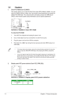
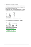
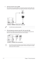
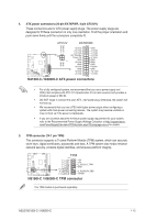
3. Chassis intrusion connector (4-1 pin CHASSIS) This connector is for a chassis-mounted intrusion detection sensor or switch. Connect one end of the chassis intrusion sensor or switch cable to this connector. The chassis intrusion sensor or switch sends a high-level signal to this connector when a chassis component is removed or replaced. The signal is then generated as a chassis intrusion event. By default, the pins labeled "Intruder" are shorted with a jumper cap. Remove the jumper caps only when you intend to use the chassis intrusion detection feature. CHASSIS N3150I-C N3050I-C +5VSB_MB Chassis Signal GND PIN 1 N3150I-C / N3050I-C Chassis intrusion connector 4. Display panel backlight power selector (3-pin BLKT_PWR_SEL) N3150I-C N3050I-C BLKT_PWR_SEL 12 23 12V 5V (Default) N3150I-C / N3050I-C Display panel backlight power selection Pins 1-2 (Default) 2-3 Setting 12V 5V ASUS N3150I-C / N3050I-C 1-9
-
 1
1 -
2
-
3
-
4
-
5
-
6
-
7
-
8
-
9
-
10
-
11
-
 12
12 -
 13
13 -
 14
14 -
 15
15 -
 16
16 -
 17
17 -
 18
18 -
 19
19 -
 20
20 -
 21
21 -
 22
22 -
23
-
24
-
25
-
26
-
27
-
28
-
29
-
30
-
31
-
32
-
33
-
34
-
35
-
36
-
37
-
38
-
39
-
40
-
41
-
42
-
43
-
44
-
45
-
46
-
47
-
48
-
49
-
50
-
51
-
52
-
53
-
54
-
55
-
56
-
57
-
58
-
59
-
60
-
61
-
62
-
63
-
64
-
65
-
66
 |
 |
