Asus N3050I-C User Guide - Page 23
N3150I-C / N3050I-C LVDS connector
 |
View all Asus N3050I-C manuals
Add to My Manuals
Save this manual to your list of manuals |
Page 23 highlights
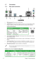
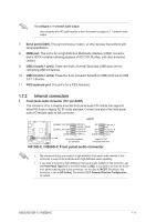
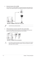
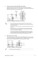
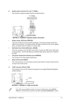
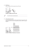
8. System panel connector (10-1 pin F_PANEL) This connector supports several chassis-mounted functions. F_PANEL +PWR LED- PWR_BTN PWR_LED+ PWR_LEDPWR GND PIN 1 HDD_LED+ HDD_LED- Ground HWRST# (NC) N3150I-C N3050I-C +HDD_LED- RESET N3150I-C / N3050I-C System panel connector • System power LED (2-pin PWRLED) This 2-pin connector is for the system power LED. Connect the chassis power LED cable to this connector. The system power LED lights up when you turn on the system power, and blinks when the system is in sleep mode. • Hard disk drive activity LED (2-pin +HDLED) This 2-pin connector is for the HDD Activity LED. Connect the HDD Activity LED cable to this connector. The HD LED lights up or flashes when data is read from or written to the HDD. • ATX power button/soft-off button (2-pin PWRBTN) This connector is for the system power button. • Reset button (2-pin RESET) This 2-pin connector is for the chassis-mounted reset button for system reboot without turning off the system power. 9. LVDS connector (40-pin LVDS) This connector is for an LCD monitor that supports Low-voltage Differential Signaling (LVDS) interface. N3150I-C N3050I-C LVDS PIN 1 N3150I-C / N3050I-C LVDS connector The LVDS output is disabled by default. To connect a LVDS monitor, set the IGD Flat Panel item in the BIOS setup to [LVDS]. See section 2.5.3 SoC Configuration for details. ASUS N3150I-C / N3050I-C 1-15
-
 1
1 -
2
-
3
-
4
-
5
-
6
-
7
-
8
-
9
-
10
-
11
-
12
-
13
-
14
-
15
-
16
-
17
-
 18
18 -
 19
19 -
 20
20 -
 21
21 -
 22
22 -
 23
23 -
 24
24 -
 25
25 -
 26
26 -
 27
27 -
 28
28 -
29
-
30
-
31
-
32
-
33
-
34
-
35
-
36
-
37
-
38
-
39
-
40
-
41
-
42
-
43
-
44
-
45
-
46
-
47
-
48
-
49
-
50
-
51
-
52
-
53
-
54
-
55
-
56
-
57
-
58
-
59
-
60
-
61
-
62
-
63
-
64
-
65
-
66
 |
 |
