Asus N3050I-C User Guide - Page 20
N3150I-C / N3050I-C Fan connectors
 |
View all Asus N3050I-C manuals
Add to My Manuals
Save this manual to your list of manuals |
Page 20 highlights
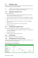
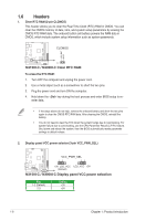
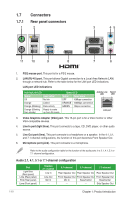
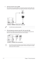
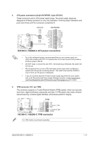
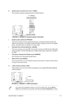
2. Serial port connector (10-1 pin COM1) This connector is for a serial (COM) port. Connect the serial port module cable to this connector, then install the module to a slot opening at the back of the system chassis. COM2 CTS DSR DTR RXD RI RTS GND TXD DCD PIN 1 N3150I-C N3050I-C N3150I-C / N3050I-C Serial port connector The COM module is purchased separately. 3. CPU and chassis fan connectors (4-pin CPU_FAN, 4-pin CHA_FAN) Connect the fan cables to the fan connectors on the motherboard, ensuring that the black wire of each cable matches the ground pin of the connector. CPU_FAN CHA_FAN N3150I-C / N3050I-C Fan connectors Do not forget to connect the fan cables to the fan connectors. Insufficient air flow inside the system may damage the motherboard components. These are not jumpers! Do not place jumper caps on the fan connectors! N3150I-C N3050I-C CPU FAN PWM CPU FAN IN +12V GND CHAFAN_PWM CHA FAN IN CHAFANPWR GND 1-12 Chapter 1: Product introduction
-
 1
1 -
2
-
3
-
4
-
5
-
6
-
7
-
8
-
9
-
10
-
11
-
12
-
13
-
14
-
 15
15 -
 16
16 -
 17
17 -
 18
18 -
 19
19 -
 20
20 -
 21
21 -
 22
22 -
 23
23 -
 24
24 -
 25
25 -
26
-
27
-
28
-
29
-
30
-
31
-
32
-
33
-
34
-
35
-
36
-
37
-
38
-
39
-
40
-
41
-
42
-
43
-
44
-
45
-
46
-
47
-
48
-
49
-
50
-
51
-
52
-
53
-
54
-
55
-
56
-
57
-
58
-
59
-
60
-
61
-
62
-
63
-
64
-
65
-
66
 |
 |
